
Dead and Live Loads: Framing Capacity, Weight Per Square Foot, Existing Roof Weight, Snow Load, Overload Consequences, Wind Uplift, Point Loads, Load Combinations
When researching “dead and live loads”, the key factors are weight per square foot, framing capacity, snow load, existing roof weight, wind uplift, overload consequences, load combinations, and point loads. For solar panels, the dead load is the steady weight of the modules, rails, and clamps, which usually adds roughly 2 to 4 pounds per square foot to a roof. Live loads change over time and include snow, wind, and the weight of people working on the roof. Your roof framing must carry both together, so rafter size, spacing, and span determine how much added weight the structure can safely hold. Snow load matters most in cold regions, where local codes set the design snow weight that the roof plus the array must support. Solar pv installers typically check these figures against the framing before a system is designed, and this article explains weight per square foot, framing capacity, and snow load in turn.
Key Takeaways
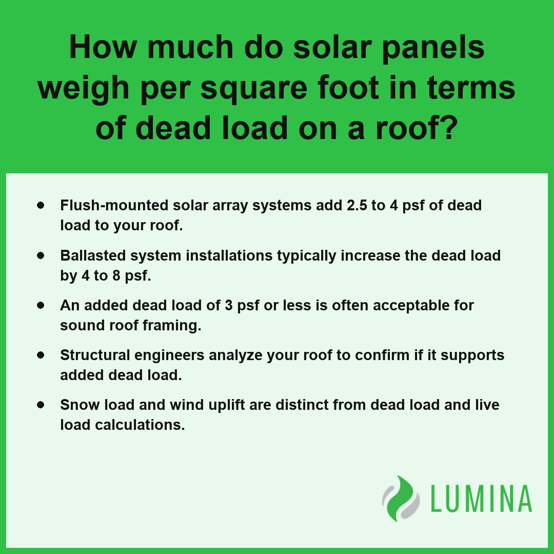
- Flush-mounted solar array systems add 2.5 to 4 psf of dead load to your roof.
- Ballasted system installations typically increase the dead load by 4 to 8 psf.
- An added dead load of 3 psf or less is often acceptable for sound roof framing.
- Structural engineers analyze your roof to confirm if it supports added dead load.
- Snow load and wind uplift are distinct from dead load and live load calculations.
How Much Do Solar Panels Weigh Per Square Foot in Dead Load Terms?
Solar panels weigh between 2.5 to 8 psf (pounds per square foot) in dead load terms, depending on whether you install a flush-mounted array or a ballasted system. The dead load of your roof consists of the weight of the modules, the racking, the wiring, and any additional materials required to secure the array to your structure. Understanding these dead and live loads is essential because they represent the cumulative pressure on your rafters, which must remain within safe limits to prevent long-term structural fatigue. Per the American Society of Civil Engineers standard ASCE 7-22, roof structures should be engineered to support the additional dead load of photovoltaic systems, which they approximate to be between 2 and 5 pounds per square foot.
| System Configuration | Estimated Dead Load (psf) | Primary Load Factors |
|---|---|---|
| Flush-Mounted Residential | 2.5 – 4.0 | Modules, racking, and mounting hardware |
| Ballasted Flat-Roof | 4.0 – 8.0 | Modules, racking, and wind uplift ballast |
| Note: Structural threshold typically requires that total added load remains below a 5% increase for existing rafters. | ||
Dead Load by Solar System Type (psf)
The weight profile of your solar array varies based on the configuration and the components required to manage environmental forces:
- Flush-mounted residential rail system: 2.5 to 4 psf (includes modules and racking).
- Ballasted flat-roof system: 4 to 8 psf (may increase if extra weight is needed to counteract wind uplift).
- Standard residential module: 40 to 50 lb per unit (60-cell or 66-cell models).
- Standard commercial module: 50 to 60 lb per unit (72-cell models, covering 17 to 22 square feet).
While an added dead load of about 3 psf or less is often acceptable for a roof in sound condition, you must ensure that the total weight does not push the existing structural members beyond a 5 percent increase in stress. Always verify the specific weight specifications provided by the manufacturer of your chosen racking and modules before finalizing your installation plan.
Can Your Roof Framing Support Solar Panels Based on Rafter Size, Spacing, and Condition?
You must confirm that your rafter size, spacing, and current condition can accommodate the additional solar array dead and live loads without increasing the existing structural stress by more than 5 percent, as verified by a structural engineer through a formal load combination analysis.
| Load Component | Load Value (psf) | Structural Impact Consideration |
|---|---|---|
| Existing Roof Structure | 15.0 psf | Baseline dead load; requires inspection for degradation. |
| Solar Array (Added) | 4.0 psf | Must not increase member stress by >5% total. |
| Combined Static Load | 19.0 psf | Requires verification of rafter span capacity. |
| Mounting Hardware | Variable | Introduces concentrated point loads on framing. |
Estimated Dead Loads (psf)
How Rafter Size and Spacing Set Framing Capacity
Your roof framing can support solar panels if the rafter size, spacing, and current structural integrity provide sufficient reserve capacity for the combined dead and live loads. Per the International Code Council, roof framing must be evaluated to ensure it can support the added dead load of solar energy systems along with the concentrated loads created by mounting hardware. Building codes generally allow for roof alterations if the added gravity load increases the stress in any member by no more than 5 percent. Because residential rafters are calculated based on the span between supports, their dimensions and the frequency of their placement determine the maximum uniform load the roof can safely carry. If your rafters are undersized or spaced widely, the added 2.5 to 4 psf (pounds per square foot) from a flush-mounted solar array may exceed design limits.
What Does Roof Condition Mean for Added Dead Load?
Roof condition dictates how well the structure manages the added dead load over time, especially when previous degradation has already compromised the wood members. An existing asphalt shingle roof over wood framing typically carries a dead load of 10 to 15 psf. If rot, moisture damage, or sagging is present, the framing lacks the safety margin required to accommodate even an additional 3 psf or less of solar equipment.
Why a Structural Engineer Reviews Aging Framing
- Identifies hidden decay in rafter heels and connections.
- Evaluates if the existing roof supports satisfy modern code requirements for total dead and live loads.
- Assesses whether reinforcement is needed to prevent long-term structural deflection.
Where Racking Attachment Spacing Creates Point Load
Racking attachment spacing creates point load concentrations at the specific rafters where your array is anchored. While solar panels distribute weight across the roof, the racking systems rely on bolts typically spaced 4 to 6 feet apart. These connections transfer both dead load and environmental forces, such as wind uplift, directly into the roof framing, necessitating that each attachment point aligns with structurally sound rafters to avoid localized failure.
Verify the thickness and structural health of your roof sheathing to ensure it can firmly hold the lag bolts required for your specific racking layout. To ensure structural compliance for your solar installation, follow these evaluation steps:- Verify the wood species and grade of the existing rafters to determine the allowable bending stress.
- Measure the clear span and the actual cross-sectional dimensions of the rafters to calculate the current structural capacity.
- Identify and account for all additional attic storage or insulation loads that may already be taxing the roof framing.
- Confirm that the mounting hardware layout aligns with the rafters to distribute point loads effectively across the framing members.
- Document any signs of rot, insect damage, or moisture-related degradation that would reduce the effective strength of the timber.
Snow Load and Solar Panels: Is Snow a Live Load?
Snow load is categorized as an environmental load separate from live load, though both represent variable forces that interact with the permanent dead load of your roof. While live load typically accounts for the transient weight of maintenance personnel, snow load is treated as a distinct, climate-dependent variable. Ground snow loads across the country range from near 0 psf to over 100 psf, and because a solar array can alter how this snow accumulates or sheds, engineers must account for the specific geometry of the racking to ensure that the combination of dead and live loads does not exceed the structural capacity of the rafters.
| Snow Loading Factor | Mechanical Impact on Solar Installations | Structural Engineering Consideration |
|---|---|---|
| Snow Drift Accumulation | Panels act as physical barriers/dams | Increased localized pressure at array boundaries |
| Unbalanced Loading | Non-uniform weight distribution across rafters | Deviation from standard uniform building code assumptions |
| Shedding Velocity | Reduced surface friction compared to shingles | Dynamic impact loads on lower roof sections |
| Combined Dead/Snow Load | Weight synergy between rack and snow depth | Application of 1.2D + 1.6S safety factor formulas |
- Snow Drift: Solar modules can act as dams, causing snow to pile up higher than normal at the lower roof edges or in valleys.
- Unbalanced Loading: The presence of a solar array may lead to uneven snow distribution, creating localized stress points that differ from the uniform loads assumed in standard building codes.
- Sliding Risk: Solar module surfaces are often smoother than asphalt shingles, which may increase the frequency or velocity of snow shedding toward lower roof sections.
- Structural Load Combinations: Engineers calculate safety using specific formulas, such as 1.2D + 1.6S for strength design, to ensure the structure survives the peak synergy between permanent weight and snow weight.
Review the historical ground snow load data for your specific region to determine if your rafters require reinforcement before installing modules that might influence snow retention patterns.
Engineers typically evaluate these additional site-specific factors when assessing solar array viability in high-snow regions:- Thermal Buildup: Solar panels retain heat and may cause intermittent melting and refreezing (ice damming) at the eaves, which adds hydrostatic pressure beyond static snow weight.
- Slope Angle Modification: The installation angle of the racking may reduce the roof’s effective pitch, preventing natural gravitational shedding and increasing the duration of the snow load.
- Wind-Driven Compaction: Airflow turbulence caused by the array gap can compress snow against the racking, increasing the density and weight per square foot compared to undisturbed ground snow.
- Fastener Pull-out Capacity: The combined shear force of wind uplift and snow sliding can exceed the withdrawal resistance of standard roof attachments if they are not specifically rated for dynamic lateral loads.
Does the 20 psf Roof Live Load Still Apply Under Fixed Solar Panels?
No, the 20 psf roof live load does not apply to the surface area covered by fixed solar panels in the same way it applies to the rest of the roof. While building codes typically mandate a minimum 20 psf live load for maintenance accessibility on open roofs, fixed solar arrays generally occupy that space and prevent standard foot traffic. Per Federal Emergency Management Agency, structural integrity assessments for these additions generally approximate a requirement that the roof system supports both the added dead load of the equipment and the original design live load for roof maintenance and snow accumulation. Instead, structural engineers adjust their load combinations to account for the interplay between dead and live loads, often treating the footprint of the array as an area where the conventional live load is superseded by the specific wind uplift and snow load requirements unique to the installation.
| Load Category | Design Factor | Application Criteria for Solar Arrays |
|---|---|---|
| Dead Load (DL) | 1.2 | Combined weight of racking, modules, and mounting hardware |
| Snow Load (SL) | 1.6 | Increased accumulation potential due to panel slope and drift |
| Wind Uplift | Varies by Zone | Pressure differential on array perimeter and corner zones |
| Live Load (LL) | Reduction | Superseded by array footprint; limited to maintenance paths |
| Stress Threshold | ≤ 5% Increase | Maximum allowable structural member deflection/stress limit |
Design Load Factor Multipliers
When calculating the capacity of your rafters, a structural engineer will evaluate how the added mass interacts with these varied criteria:
- Reductions in roof live load due to the permanent coverage of the solar array.
- Specific load combinations, such as using 1.2 times the dead load plus 1.6 times the snow load for strength design.
- Adjustments for wind uplift that can significantly exceed the downward pressure of the solar array itself.
- Validation that any structural member does not exceed a 5 percent increase in stress due to the new installation.
Compare the anticipated load combination outputs against your rafter span tables to ensure your roof structure remains within its deflection limits.
To ensure compliance and safety during the structural assessment of a solar installation, consider these additional engineering requirements:- Verify that the existing roof rafters or trusses are not compromised by the penetration points of the mounting hardware.
- Perform a localized analysis of the roof deck’s ability to withstand the concentrated point loads exerted by individual mounting feet.
- Evaluate the impact of solar panels on the roof’s fire classification and thermal ventilation requirements.
- Confirm that the electrical conduits and wire management systems do not introduce additional significant dead loads or interfere with drainage patterns.
- Assess the age and remaining service life of the roofing material to ensure it can support the system for its expected duration.
How Much Ballast Does a Flat-Roof Solar Array Need, and How Does It Change Dead Load?
A flat-roof solar array requires a ballasted system that adds between 4 to 8 psf to your roof, though wind uplift requirements can force this dead load much higher depending on your building height and site exposure. Because these systems rely on sheer mass rather than roof-penetrating anchors to counter wind uplift, the weight is distributed across the membrane surface to prevent the array from sliding or tipping during extreme weather events. Per American Society of Civil Engineers, ballasted solar arrays must be engineered to withstand wind uplift and sliding by determining the minimum ballast weight based on site-specific roof zone pressures and the friction coefficient between the racking hardware and the roof. Balancing these dead and live loads is critical, as the ballast weight acts as a constant downward force that competes with the structural capacity of your roof framing.
Dead Load Impact by Solar System Type (psf)
| System Type | Dead Load Impact (psf) | Mechanism for Stability |
|---|---|---|
| Flush-Mounted (Rail) | 2.5 to 4 psf | Mechanical fasteners |
| Standard Ballasted | 4 to 8 psf | Concrete blocks or trays |
| High-Wind Ballasted | Over 8 psf | Increased block density |
When you add this significant permanent weight, you must ensure your roof membrane can support the concentrated pressure beneath each ballast tray without compressing or tearing. While a ballasted system avoids the risk of leaks associated with roof penetrations, the additional mass requires that you verify the internal ceiling structure can handle the long-term stress of the added dead load without causing deflection or fatigue. Inspect the condition of your existing roof insulation to ensure it is rigid enough to support the ballast blocks without losing its thermal properties over time.
Before proceeding with a ballasted solar installation, consider these essential structural and site-specific requirements:- Conduct a formal structural load analysis to verify that the existing roof joists and deck can accommodate the additional dead load without exceeding deflection limits.
- Install protective slip sheets or sacrificial membrane pads between ballast trays and the roof surface to prevent abrasion and localized pressure damage.
- Verify that the rooftop drainage system remains unobstructed, as ballast arrays can alter water runoff patterns and potentially create ponding areas.
- Coordinate with a certified roofing contractor to ensure that adding permanent weight does not void existing roof material warranties.
- Confirm that the building’s fire classification rating remains compliant with local building codes once the racking and ballast materials are installed.
Frequently Asked Questions
How does the weight of my existing roof covering, like tile or asphalt shingles, affect how much solar panel dead load it can take?
The weight of your existing roof covering dictates remaining capacity, as asphalt shingles over wood framing add 10 to 15 psf while tile adds 10 to 20 psf. Because residential solar arrays typically add 2.5 to 4 psf, a structural engineer must confirm your rafters can support the total.
How does wind uplift factor into solar panel dead and live load calculations?
Wind uplift acts as a critical force that can exceed the dead load of the solar array many times over at design wind speeds of 110 to 180 mph. Engineers must account for these forces in specific load combinations to ensure the connection to the roof structure remains secure and intact.
What happens if solar panel dead and live loads overload a roof?
Overloading a roof may cause structural failure if the added stress exceeds the 5 percent limit allowed by building codes for alterations. You should verify your rafter size, species, and current condition, as most experts suggest that an added load of about 3 psf or less is generally acceptable.
What load combinations do engineers use for solar panel dead load, snow, and wind, such as 1.2D + 1.6S?
Engineers use load combinations such as 1.2D + 1.6S for strength design, D + S for allowable stress design, and 0.6D + 0.6W for uplift checks. These calculations account for the specific interaction between the structure and environmental factors like snow load, which can range from near 0 to 100 psf.
How do racking attachment spacing and lag screw embedment create point loads on rafters under solar panels?
Racking attachments create point loads by concentrating weight and uplift forces onto specific rafters at intervals of 4 to 6 feet apart. Each lag screw typically requires 2.5 inches of embedment to manage these forces, which is essential for safely supporting the combined weight of the dead and live loads.