Angle of Incidence Optics: Cosine Loss, Tilt and Orientation, Anti-reflective Coating, Glass Reflection, Annual Energy Loss, Seasonal and Daily Variation, Definition, Tracking
Angle of incidence optics describes how the angle at which sunlight meets a panel surface changes the light absorbed. Key aspects include tilt and orientation, cosine loss, glass reflection, anti-reflective coating, seasonal and daily variation, annual energy loss, tracking, and definition. Sunlight that strikes a panel head-on is absorbed most efficiently, while light arriving at a steeper slant is partly lost through cosine loss and reflection from the cover glass. An anti-reflective coating on that glass reduces the reflected share, especially at wider angles. The direction your panels face and their tilt set the typical angle at which light arrives, and that angle shifts across the day and between seasons. These factors shape how much energy a solar panel installation yields over a full year. The sections below explain cosine loss, glass reflection, anti-reflective coatings, tilt and orientation, and seasonal and daily variation in turn.
Key Takeaways
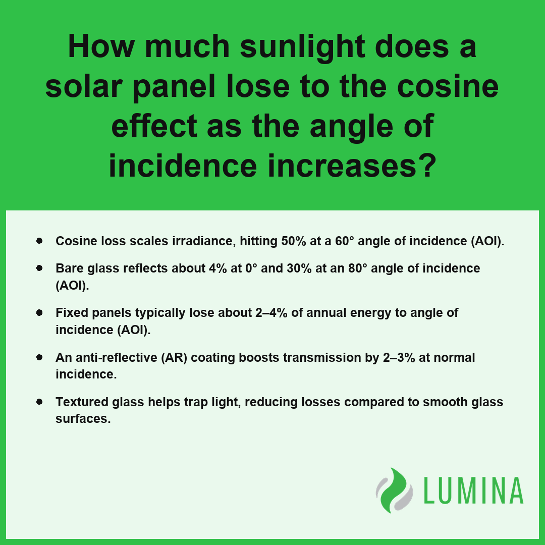
- Cosine loss scales irradiance, hitting 50% at a 60° angle of incidence (AOI).
- Bare glass reflects about 4% at 0° and 30% at an 80° angle of incidence (AOI).
- Fixed panels typically lose about 2–4% of annual energy to angle of incidence (AOI).
- An anti-reflective (AR) coating boosts transmission by 2–3% at normal incidence.
- Textured glass helps trap light, reducing losses compared to smooth glass surfaces.
How Much Sunlight Does a Solar Panel Lose to Cosine Loss as the Angle of Incidence Increases?
The sunlight a solar panel loses to cosine loss as the angle of incidence (AOI) increases is a direct consequence of the diminishing effective surface area available to intercept light rays as they stray from the panel normal. Because solar panels operate as flat collectors, they obey Lambert’s cosine law, meaning the irradiance reaching the cell surface is reduced in proportion to the cosine of the AOI. Per the National Renewable Energy Laboratory, the power output of a photovoltaic module follows this principle, as the intensity of incident solar radiation is proportional to the cosine of the angle between the sun’s rays and the module’s surface normal. When the sunlight strikes at a 0° AOI, you capture 100% of the available potential, but this efficiency drops mathematically as the sun moves across the sky.
Intercepted Irradiance by Angle of Incidence
How the Panel Normal Sets the Cosine Loss
The panel normal acts as the reference point for all angle of incidence optics. If you are tracking the sun, you minimize this angle to keep your yield high. Without a solar tracker, you accept a performance curve that degrades throughout the day. The following table illustrates how the geometric interception of sunlight drops based on the AOI:
| Angle of Incidence | Intercepted Irradiance |
|---|---|
| 0° | 100% |
| 30° | 86.6% |
| 45° | 70.7% |
| 60° | 50% |
| 75° | 25.9% |
Why 60° Is the Halfway Point
At a 60° angle of incidence, the geometric projection of the sun onto your panel is exactly half of the energy it would receive at a 0° angle. This rapid decay explains why the total annual energy loss from angle effects for fixed panels typically remains between 2–4%, as the most productive hours of the day occur when the sun is closer to the panel normal.
Does Cosine Loss Matter at Small Angles?
No, cosine loss does not significantly penalize your system at small angles, as the function remains relatively flat near the center. Between 0° and 20°, the drop in irradiance is negligible, meaning your system performs with high efficiency during the midday period even without complex tracking mechanics.
Observe the orientation of your array relative to the path of the sun to identify if you are frequently exceeding a 60° angle of incidence during peak production hours.
To mitigate these losses in static installations, consider these optimization strategies:- Optimize tilt angles seasonally to better align the panel normal with the sun’s average midday elevation.
- Prioritize south-facing orientations (in the Northern Hemisphere) to ensure the 0° AOI occurs during the period of peak solar intensity.
- Utilize bifacial modules to capture albedo light, which helps offset power deficits caused by high AOI direct radiation.
- Install panels with high-transmittance, anti-reflective glass coatings to minimize additional reflection losses that occur concurrently with cosine effect at steep angles.
Why Panel Glass Reflects More Light at High Angles of Incidence
Panel glass reflects more light at high angles of incidence because of the physical nature of Fresnel reflection, which dictates how light transitions between media with different refractive indices. When sunlight passes from air into the glass cover, it must cross an interface where the sudden change in optical density causes a portion of the light to bounce off the surface rather than entering the solar cells. This behavior is fundamental to angle of incidence optics; while bare glass reflects only about 4% of light at normal incidence, that loss grows significantly as the light path moves away from the panel normal.
| Angle of Incidence (Degrees) | Light Path Classification | Surface Reflection Penalty | Optical Transmission Impact |
|---|---|---|---|
| 0° | Normal | 4% | High (96% entry) |
| 60° | Oblique | 10% | Moderate |
| 80° | Deep Oblique | 30% | Significant |
| 90° | Grazing | 100% | Total Rejection |
Reflection Loss by Angle of Incidence
The progression of these losses follows a non-linear curve that accelerates rapidly once the angle exceeds 60°. You can see the relationship between the incoming path and the resulting optical penalty in the following comparison of light reflection at different angles:
- Normal incidence (0°): About 4% reflection loss.
- Oblique incidence (60°): Approximately 10% reflection loss.
- Deep oblique incidence (80°): Approximately 30% reflection loss.
- Grazing incidence (90°): 100% reflection loss as light fails to penetrate the surface.
Because the reflected share remains relatively low until the light path reaches a steep slant, the total energy reduction is most noticeable during early morning and late afternoon hours. Per Sandia National Laboratories, anti-reflective coatings are engineered to mitigate these issues, but performance degradation remains an inherent characteristic of flat-plate photovoltaic modules when sun angles are low. You should examine the manufacturer’s provided incidence angle modifier (IAM) data for your specific module to determine how its glass surface handles these shifts throughout the day.
Several external factors can exacerbate these reflection losses in real-world photovoltaic deployments:- Surface contamination, such as dust or salt buildup, scatters incoming light and increases the effective reflection at non-normal angles.
- Condensation or morning dew creates a secondary air-water-glass interface, which can temporarily amplify reflection losses until the moisture evaporates.
- Anti-reflective coatings (ARC) are frequently applied during manufacturing to chemically disrupt the refractive index transition, shifting the reflection curve downward.
- Textured glass patterns, such as pyramid or prismatic surfaces, redirect oblique light to promote internal light trapping and reduce outward reflection.
Do Anti-Reflective Coatings Improve Performance at Steep Angles of Incidence?
Yes, anti-reflective (AR) coatings improve performance at steep angles of incidence (AOI) by minimizing the Fresnel reflection that otherwise causes significant energy loss. While bare glass typically reflects about 4% of light at normal incidence, its reflective losses escalate rapidly as light strikes from sharper angles. An AR coating, often composed of a porous silica layer roughly 100–130 nm thick, serves to disrupt this reflection, providing a transmission gain of about 2–3% at 0° and preserving a higher percentage of available light as the angle of incidence optics shift toward the horizon.
Untreated Glass Reflection by AOI
The following table illustrates how these optical modifications assist in maintaining energy capture compared to untreated glass surfaces:
| AOI Condition | Untreated Glass Reflection | Effect of AR Coating |
|---|---|---|
| 0° (Normal) | ~4% | 2–3% transmission gain |
| 60° | ~10% | Significant reduction in loss |
| 80° | ~30% | Substantial improvement in intake |
In addition to these chemical coatings, the use of textured glass further manages angle of incidence optics by scattering incoming light and flattening the incidence angle modifier (IAM) curve, which is critical for maximizing performance during early morning and late afternoon hours. Lawrence Berkeley National Laboratory reports that the application of nanostructured anti-reflective layers effectively broadens the range of optimal light capture for solar modules, resulting in improved daily energy yields particularly during early morning and late afternoon hours when steep incident angles dominate. When selecting panels, prioritize products that utilize both AR-coated and textured surfaces to ensure high-efficiency light capture throughout the day.
Beyond the optical properties described, several environmental and mechanical factors influence the long-term effectiveness of these glass modifications:- Hydrophilic properties of silica-based coatings often provide a self-cleaning effect, reducing the accumulation of dust and particulate matter.
- Surface texture depth must be precisely calibrated to balance optimal light scattering against the risk of increased soil adhesion.
- Hardness levels of nanostructured layers determine the module’s resistance to mechanical abrasion during cleaning or high-wind debris impact.
- Chemical durability of the coating is essential to prevent degradation from ultraviolet radiation and environmental moisture over the solar panel’s operational lifespan.
Best Panel Tilt and Panel Azimuth for Your Roof
Best panel tilt and panel azimuth for your roof are the primary variables you control to manage the angle of incidence optics that dictate your system’s daily energy harvest. By aligning your installation to minimize the angle of incidence (AOI) during the peak solar hours, you maximize the direct irradiance captured by the cells. While your roof’s existing architecture limits your choices, balancing these two factors ensures that sunlight strikes the panel normal as squarely as possible throughout the year. Because residential roof tilts commonly range from 15° to 40°, most systems remain effective, though deviations from an optimal south-facing orientation necessitate a larger tilt adjustment to maintain efficiency.
| Optimization Strategy | Ideal Tilt Alignment | Primary Benefit |
|---|---|---|
| Standard Performance | Equal to site latitude | Balanced year-round solar capture |
| Summer Peak Demand | Latitude minus 15° | Minimized AOI during high-elevation days |
| Winter Peak Demand | Latitude plus 15° | Optimized capture for low-angle winter sun |
| Maximum Daily Yield | True South (180°) | Consistent irradiance throughout peak hours |
Typical Roof Tilt Ranges (Degrees)
- True South Azimuth: For northern hemisphere locations, orienting your panels toward true south minimizes the angle of incidence optics variability throughout the day. Per the Department of Energy, panel azimuth is defined by the compass direction of the array, and true south generally serves as the standard for maximizing annual energy production throughout most of the United States.
- Latitude-Matching Tilt: Setting your panel tilt equal to your site latitude provides a balanced compromise for capturing high-noon sun in both summer and winter seasons.
- Summer vs. Winter Bias: If your energy needs peak during summer, a lower tilt closer to your latitude minus 15° can reduce the average AOI during long, high-elevation days.
- Energy Capture Trade-offs: Selecting a flatter tilt of 15° increases the likelihood of capturing early morning and late afternoon light, whereas steeper tilts near 40° prioritize winter production when the sun remains lower in the sky.
Use an online solar mapping tool to visualize your specific roof orientation and calculate how much annual production you would sacrifice by choosing a sub-optimal tilt before finalizing your mounting bracket strategy.
Why Angle of Incidence Optics Change From Summer to Winter and Morning to Evening
Why angle of incidence optics change from summer to winter and morning to evening is primarily a result of the shifting solar zenith angle relative to your fixed panel orientation. Because your panels remain in a static position, the path of the sun through the sky dictates the angle of incidence (AOI) throughout the day and across the seasons. Per the National Oceanic and Atmospheric Administration, seasonal shifts in the sun’s maximum solar elevation angle are approximately caused by the 23.5-degree tilt of the Earth, which necessitates adjustments in panel orientation to maintain consistent solar flux across different months. In the summer, the sun reaches a higher solar elevation, typically resulting in an AOI closer to the panel normal and more efficient energy capture. Conversely, during the winter months, the lower solar arc increases the AOI, leading to greater Fresnel reflection and increased cosine loss. For instance, at a 40° latitude, the noon AOI for a flat panel shifts significantly between solstices.
Typical Annual Energy Loss for Fixed Panels
| Time/Season | Typical Noon AOI |
|---|---|
| Summer Solstice | About 17° |
| Winter Solstice | About 63° |
Daily performance also follows this optical trend. During the early morning and late evening, the sun strikes the panel at a glancing angle, significantly increasing the AOI and reducing the incidence angle modifier (IAM). While fixed panels experience typical annual energy losses of about 2–4% due to these changing dynamics, you can mitigate these optical penalties by considering the tracking capabilities of your system.
Compare your current annual energy production estimates against the projected output of a single-axis solar tracker to determine if the 15–25% potential gain justifies the mechanical complexity for your specific roof geometry.
Mitigating the impact of these optical losses requires consideration of several installation and environmental variables:- Surface soiling, such as dust or snow accumulation, disproportionately exacerbates losses when the sun is at a low angle of incidence.
- Panel azimuth orientation influences the specific time of day when peak cosine loss occurs, potentially shifting energy production windows.
- Anti-reflective coatings on glass surfaces are specifically engineered to minimize Fresnel reflection losses during high AOI periods.
- Diffuse irradiation, which accounts for a larger percentage of total light in winter, is less sensitive to the angle of incidence than direct beam radiation.
Frequently Asked Questions
What is the angle of incidence in solar panel optics and how is it measured from the panel?
The angle of incidence (AOI) in solar panel optics is the angle between incoming light rays and the panel normal. You measure this angle from the panel normal, not from the surface, where 0° indicates light hitting the surface straight on and 90° indicates light grazing the surface.
How do you calculate the angle of incidence on a tilted solar panel using sun position and panel orientation?
You calculate the angle of incidence by determining the solar zenith angle and solar elevation relative to the panel tilt and panel azimuth. At 40° latitude, a flat panel at the summer solstice sees a noon AOI of about 17°, whereas the winter solstice results in an AOI of about 63°.
How much annual energy do angle of incidence losses cost a fixed solar panel system compared with a tracker?
Fixed solar panels typically lose about 2–4% of annual energy due to angle of incidence effects, while well-aligned solar tracker systems can reduce these losses to below 1–2%. High AOI leads to significant cosine loss and Fresnel reflection, which sharply reduce output during the early morning and late afternoon.
Is a single-axis or dual-axis solar tracker worth it for reducing angle of incidence losses?
Yes, a solar tracker is often worth it for reducing angle of incidence losses because trackers can add roughly 15–25% in energy compared to a fixed tilt. By keeping the panel normal aligned closer to the sun, you minimize the sharp energy drops caused by cosine loss and high-angle Fresnel reflection.
What is an incidence angle modifier and how do solar modeling tools use it to account for angle of incidence optics?
The incidence angle modifier (IAM) is a factor between 0 and 1 describing relative optical transmission used by tools like PVsyst or SAM to calculate angle of incidence optics. Models like ASHRAE or physical Fresnel equations help tools estimate efficiency gains from features like an anti-reflective (AR) coating or textured glass.