
MC4 Connector: Voltage Rating, Current Rating, Cable Size, Compatibility, Weather Rating, Crimping Method, Contact Material, Price, Service Life, Locking and Disconnection
An mc4 connector is a single-contact, waterproof plug-and-socket fitting that joins photovoltaic cables and links solar modules into electrical strings. Key aspects include current rating, voltage rating, compatibility, cable size, crimping method, weather rating, price, contact material, locking and disconnection, and service life. Each connector pairs a male and a female end that snap together and lock, forming a sealed, low-resistance joint that keeps moisture and dust out. In a typical solar panel installation PA setup, you find these fittings on the leads of every module, where they carry direct current from panel to panel and on to the inverter. Their performance depends on matching the current and voltage ratings to your array, using the correct cable size, and joining parts that are truly compatible with one another. The sections below explain each of these ratings, the cable diameters the fittings accept, and the crimping method used to attach the metal contacts to the conductor.
Key Takeaways
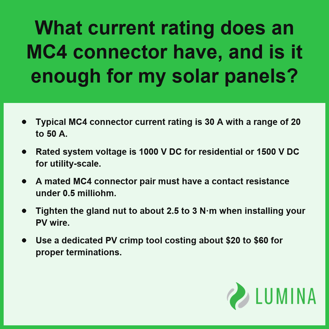
- Typical MC4 connector current rating is 30 A with a range of 20 to 50 A.
- Rated system voltage is 1000 V DC for residential or 1500 V DC for utility-scale.
- A mated MC4 connector pair must have a contact resistance under 0.5 milliohm.
- Tighten the gland nut to about 2.5 to 3 N·m when installing your PV wire.
- Use a dedicated PV crimp tool costing about $20 to $60 for proper terminations.
What Current Rating Does an MC4 Connector Have, and Is It Enough for Your Solar Modules?
The typical current rating of an MC4 connector is 30 A, which is sufficient for the vast majority of modern solar modules used in residential and commercial installations. Per the International Electrotechnical Commission, Standard 62852 establishes the design and testing requirements for these components, typically rating individual connectors for electrical currents ranging between 20 and 30 amperes depending on the contact diameter and wire cross-section used. This 30 A standard provides an essential safety margin for modules that typically feature short-circuit currents ranging from 10 to 20 A.
Typical Current Ranges (Amperes)
How Contact Resistance and Heat Limit Current
Current-carrying capacity is restricted by the heat generated across the internal connection. Each MC4 connector utilizes a tin-plated copper contact designed to maintain a contact resistance of under 0.5 milliohm per mated pair. If this resistance increases—due to poor crimping or oxidation—the junction generates excessive heat, potentially damaging the UV-resistant thermoplastic housing and causing localized resistance to rise further, leading to a thermal runaway event.
Is 30 A Enough for Your Array?
For most string-based solar modules, 30 A is more than adequate because string currents rarely exceed the 20 A limit. However, when you connect multiple high-output modules in parallel, the total current can quickly exceed the rating of a single connection point.
When to Use a Branch Connector or Combiner Box
- Branch connectors: Use only for small arrays where the total current remains well below 30 A.
- Combiner boxes: Required when the sum of parallel strings exceeds the rated current of your wiring or connectors.
- Overcurrent protection: Essential when the source circuit current potential exceeds the maximum fuse rating of the modules.
Why Cable Size Changes the Safe Current
The total current capacity is limited not just by the MC4 connector, but by the physical size of the PV wire paired with it. Using a wire gauge that is too small for the anticipated current will cause the cable itself to overheat before the connector reaches its limit.
| PV Wire Size | Common Application |
|---|---|
| 2.5 mm² | Low-power, small-scale modules |
| 4 mm² | Standard residential modules |
| 6 mm² | High-amperage modules or long runs |
Always verify the short-circuit current of your specific solar modules on the manufacturer’s datasheet to confirm it remains below the 30 A threshold of your chosen hardware.
You should implement a branch connector or combiner box in the following scenarios:- When the sum of the short-circuit currents from parallel-connected strings exceeds 30 A.
- When you need to reduce voltage drop by consolidating multiple smaller-gauge home runs into a single larger-gauge conductor.
- When local electrical codes require individual overcurrent protection for each parallel string.
- When the physical space or layout constraints prevent running multiple individual cable pairs to the inverter input.
MC4 Connector Voltage Rating: 1000 V DC or 1500 V DC?
The MC4 connector voltage rating is either 1000 V DC or 1500 V DC, with the specific requirement determined by the design and scale of your electrical array. Residential systems typically rely on the 1000 V DC standard, whereas utility-scale installations often necessitate the 1500 V DC rating to accommodate longer strings and reduce overall system losses. You must ensure that every component in your circuit, including the MC4 connector, carries a voltage rating equal to or greater than the maximum open-circuit voltage of your string, especially under the lowest expected ambient temperatures.
| System Application Class | Voltage Rating (DC) | Primary Operational Objective | Infrastructure Impact |
|---|---|---|---|
| Residential Standard | 1000 V | Standardized string configuration | Baseline component compatibility |
| Utility-Scale | 1500 V | Optimized energy transmission | Reduced cabling and string counts |
MC4 Connector Voltage Ratings (V DC)
When selecting your hardware, consider the following distinctions between the two common industry standards:
- 1000 V DC: The conventional standard for smaller residential solar module arrays, widely available and sufficient for most standard string lengths.
- 1500 V DC: Engineered for large-scale projects to allow for higher string voltages, which effectively minimizes the total number of required strings and cabling.
- Component Matching: All mated connectors in a single circuit must meet the same voltage certification to prevent electrical arc failure or insulation breakdown.
Per Underwriters Laboratories, UL 6703 safety standards provide testing protocols that approximate the insulation and creepage requirements necessary for MC4 connectors to function safely in either 1000 V or 1500 V DC solar installations. Verify the technical datasheet of your solar module to confirm the maximum system voltage and match it with an MC4 connector that explicitly carries a corresponding safety certification.
To ensure your hardware selections maintain system integrity, follow these technical best practices:- Verify the manufacturer’s UL or IEC certification specifically for the intended voltage class to ensure regulatory compliance.
- Inspect connectors for physical damage or manufacturing defects, as voltage leakage risk increases significantly in 1500 V DC environments.
- Maintain compatibility between connector brands, as cross-mating different manufacturers can lead to poor seals and arcing hazards.
- Account for the temperature coefficient of your solar modules, which can cause voltage spikes in cold weather that exceed the connector’s rating.
Can You Mix MC4 Connectors From Different Brands?
No, you should not mix an MC4 connector from one manufacturer with another brand, even if they appear physically identical. While many products are marketed as an MC4-compatible connector, internal tolerances for the tin-plated copper contact and the specific dimensions of the thermoplastic housing can vary between companies. Mixing brands often leads to a loose fit, which increases contact resistance beyond the standard 0.5 milliohm per mated pair and risks localized overheating or moisture ingress that defeats the IP67 or IP68 seal rating. Per the National Fire Protection Association, the National Electrical Code section 690.33 requires that all connectors in photovoltaic systems be polarized or keyed to prevent improper mating and must be rated for the application to maintain safety.
| Risk Factor | Technical Consequence of Mixing Brands | Standard/Certification Impact |
|---|---|---|
| Electrical Contact | Increased resistance >0.5 mΩ; localized heating risks | Violates NEC 690.33 (Safety/Polarization) |
| Mechanical Interface | Incompatible locking tabs; gland nut seal failure | Voids UL 6703 / IEC 62852 certification |
| Environmental Seal | Moisture ingress; loss of IP67/IP68 rating | Failure of standardized safety testing |
| Material Integrity | Thermal expansion rate mismatch; UV degradation | Invalidation of manufacturer safety ratings |
Operating Temperature Range (°C)
- Mechanical Incompatibility: Different brands may use unique locking tabs, making it difficult to engage or disengage the connection with an MC4 spanner.
- Gland Nut Mismatches: The threading and internal seal diameters of the gland nut are often proprietary; using mismatched parts will fail to grip the PV wire correctly, compromising weather resistance.
- Certifications: Manufacturers certify their connectors as a complete, tested set according to standards like IEC 62852 or UL 6703; substituting half of the connection voids these safety certifications.
- Material Degradation: Variations in the UV-resistant thermoplastic blends mean that two different brands may expand or weather at different rates when exposed to the typical operating temperature range of -40°C to +85°C.
Always verify that both the male connector and the female connector originate from the same production line or certified product series before beginning your installation.
Follow these best practices to ensure the long-term integrity of your solar cable connections:- Procure all mating connector pairs from the same manufacturer and original product line to ensure design compatibility.
- Utilize dedicated MC4-rated crimping tools calibrated to the specific terminal manufacturer’s specifications for a gas-tight connection.
- Perform a physical pull test on every crimped connection before securing the cable gland to verify mechanical retention.
- Apply a small amount of non-conductive, silicone-based dielectric grease to the connector seals if operating in high-humidity or coastal environments to enhance moisture resistance.
- Avoid installing connectors under direct sunlight when temperatures are at the extremes of the thermal rating to prevent plastic housing stress.
What PV Wire Size Fits an MC4 Connector?
The PV wire size that fits an MC4 connector is determined by the internal contact capacity and the physical diameter of the cable-gland seal, which must effectively grip the wire insulation to maintain an IP67 or IP68 environmental rating. Per the International Electrotechnical Commission, industry standards adopted in the United States for PV connector compatibility define specific terminal ranges, generally requiring the wire to be matched to the internal ferrule diameter to ensure both the water-tight integrity and the strain relief rating of the connector housing. When selecting components for your solar module array, you must ensure that your choice of conductor matches the internal design of the specific MC4 connector model you have purchased, as the seal must compress evenly around the outer diameter of the PV wire—typically between 5.5 and 7.5 mm—to prevent moisture ingress.
| Conductor Size (Metric) | Standard AWG Equivalent | Typical Application Use Case | Standard Insulation OD Range |
|---|---|---|---|
| 2.5 mm² | 14 AWG | Low-current configurations / Small arrays | 5.5 mm – 7.5 mm |
| 4.0 mm² | 12 AWG | Standard residential installations | 5.5 mm – 7.5 mm |
| 6.0 mm² | 10 AWG | High-current outputs / Long string runs | 5.5 mm – 7.5 mm |
PV Wire Cross-Sectional Area (mm²)
- 2.5 mm² (roughly 14 AWG): Suitable for smaller arrays or specific low-current module configurations.
- 4 mm² (roughly 12 AWG): The most common standard for typical residential solar installations.
- 6 mm² (roughly 10 AWG): Often selected for longer string runs to minimize voltage drop or for modules with higher current outputs.
Always verify the compatibility between the specific cable-gland diameter of your chosen MC4 connector and the outside diameter of your PV wire before attempting assembly to ensure a watertight seal.
Follow these best practices to ensure a secure and long-lasting connection when crimping MC4 connectors:- Use a dedicated ratcheting crimping tool specifically calibrated for solar contacts to ensure a gas-tight mechanical connection.
- Strip the wire insulation to the exact length specified by the connector manufacturer, typically 6 mm to 8 mm, to avoid damaging the copper strands.
- Verify that the locking tabs on the internal contact “click” audibly into place inside the plastic housing before tightening the cable gland.
- Apply a consistent, firm torque to the back nut to ensure the internal seal compresses fully against the wire jacket, guaranteeing the moisture-proof seal.
- Avoid reusing connectors, as the internal contact tabs and sealing gaskets are designed for single-use integrity.
How to Crimp an MC4 Connector Step by Step
Crimping an MC4 connector is the essential process for creating a reliable, weather-resistant connection between your PV wire and the solar module leads. Achieving a low-resistance joint depends on using the proper tools and following a specific sequence to ensure the metal contact is permanently bonded to the conductor.
| Parameter | Specification / Requirement | Purpose |
|---|---|---|
| Insulation Strip Length | 7 to 9 mm | Prevents conductor damage and ensures contact fit |
| Gland Nut Torque | 2.5 to 3 N·m | Achieves IP67 moisture-proof seal integrity |
| Crimp Tooling | Calibrated PV-specific tool | Guarantees permanent mechanical and electrical bond |
| Connector Engagement | Audible “Click” | Confirms internal locking mechanism activation |
Typical Stripping and Torque Requirements
- Strip approximately 7 to 9 mm of insulation from the end of the PV wire using a wire stripper, ensuring you do not nick or cut any of the copper strands.
- Insert the stripped wire into the contact and position it securely within the jaws of a dedicated PV crimp tool to ensure a secure mechanical and electrical bond. Per the American National Standards Institute, it is important to remember that technical standards for photovoltaic connectors dictate that crimp contacts must be installed using a calibrated tool matched specifically to the wire gauge and contact type to guarantee electrical integrity.
- Slide the crimped contact into the back of the MC4 connector housing until you hear a distinct click, which confirms the internal locking mechanism has engaged.
- Slide the seal and gland nut onto the cable, then tighten the gland nut onto the housing to a torque of about 2.5 to 3 N·m to ensure an IP67-rated moisture-proof seal.
- Required Components: Male or female contact, connector housing, gland nut, and cable seal.
- Tools Needed: Wire strippers, PV crimp tool, and an MC4 spanner.
- Verification: Pull gently on the wire after crimping to ensure the contact is locked firmly inside the housing.
Test the integrity of your crimped joints by performing a pull-test to ensure the conductor remains locked securely inside the contact before you snap the connectors together.
Follow these essential assembly practices to ensure the long-term reliability of your solar connections.- Inspect the contact pin for debris or oxidation before inserting the stripped wire.
- Ensure that the copper strands are fully visible through the inspection window of the contact crimp barrel.
- Slide the cable gland and rubber seal onto the wire jacket before crimping the contact.
- Verify the polarity of the connectors before snapping the male and female halves together.
- Use a dedicated pair of MC4 disconnect tools to separate connectors, as manual disconnection is prohibited by safety standards.
Frequently Asked Questions
Are MC4 connectors waterproof and can they handle extreme temperatures?
Yes, MC4 connectors are waterproof and designed to handle extreme temperatures, as they feature a UV-resistant housing rated IP67 when mated and an operating temperature range of -40°C to +85°C. Many models are also rated IP68, providing protection against temporary immersion in water while exposed to harsh environmental conditions.
What are MC4 connector contacts made of, and why does contact resistance matter?
MC4 connector contacts consist of a tin-plated copper pin and spring-type socket, maintaining a typical contact resistance under 0.5 milliohm per mated pair. Low resistance is essential to minimize power loss and prevent heat buildup, ensuring the connection remains stable and efficient while carrying currents up to 30 A.
How much do MC4 connectors and the tools to install them cost?
Loose MC4 connector pairs cost roughly $1 to $4 in bulk, while a dedicated PV crimp tool costs about $20 to $60. Additionally, an MC4 spanner, which is necessary for safe disconnection, typically costs between $3 and $10, making the total setup quite affordable for most solar module installations.
How do you safely disconnect an MC4 connector, and why do you need a spanner tool?
You safely disconnect an MC4 connector by using an MC4 spanner to release the locking mechanism, a safety feature designed to prevent accidental disconnection under load. Attempting to pull the connectors apart without this tool can damage the locking tabs, potentially creating a hazardous electrical condition or connection failure.
How long do MC4 connectors last, and what causes them to fail early?
MC4 connector failure is often caused by poorly crimped contacts or water ingress from an unseated gland nut tightened incorrectly, rather than inherent design age. To maximize longevity, always use a dedicated PV crimp tool and ensure the gland nut is tightened to the recommended 2.5 to 3 N·m torque.