
Parallel Circuits: Current, Voltage, Resistance, Series Comparison, Shade Tolerance, Power, Inverter Limits, Overcurrent Protection, Battery Banks, Wire Size
Parallel circuits are electrical arrangements in which each component connects across the same two points, giving current multiple independent paths. Key aspects include voltage, current, series comparison, resistance, power, shade tolerance, overcurrent protection, inverter limits, wire size, and battery banks. In a solar array, wiring panels this way keeps the voltage equal to that of a single panel while the currents from each panel add together. Resistance in each branch is independent, so shading or failure in one panel does not cut off the others, and the total resistance falls as branches are added. Power output equals the shared voltage multiplied by the combined current, which is why you see this layout used to raise amperage for charge controllers and inverters. When you plan a solar panel installation Washington DC, the choice between this wiring and series strings affects voltage limits, cable sizing, and performance under partial shade. This article goes on to explain voltage, current, resistance, and power in these circuits, followed by a direct comparison with series wiring.
Key Takeaways
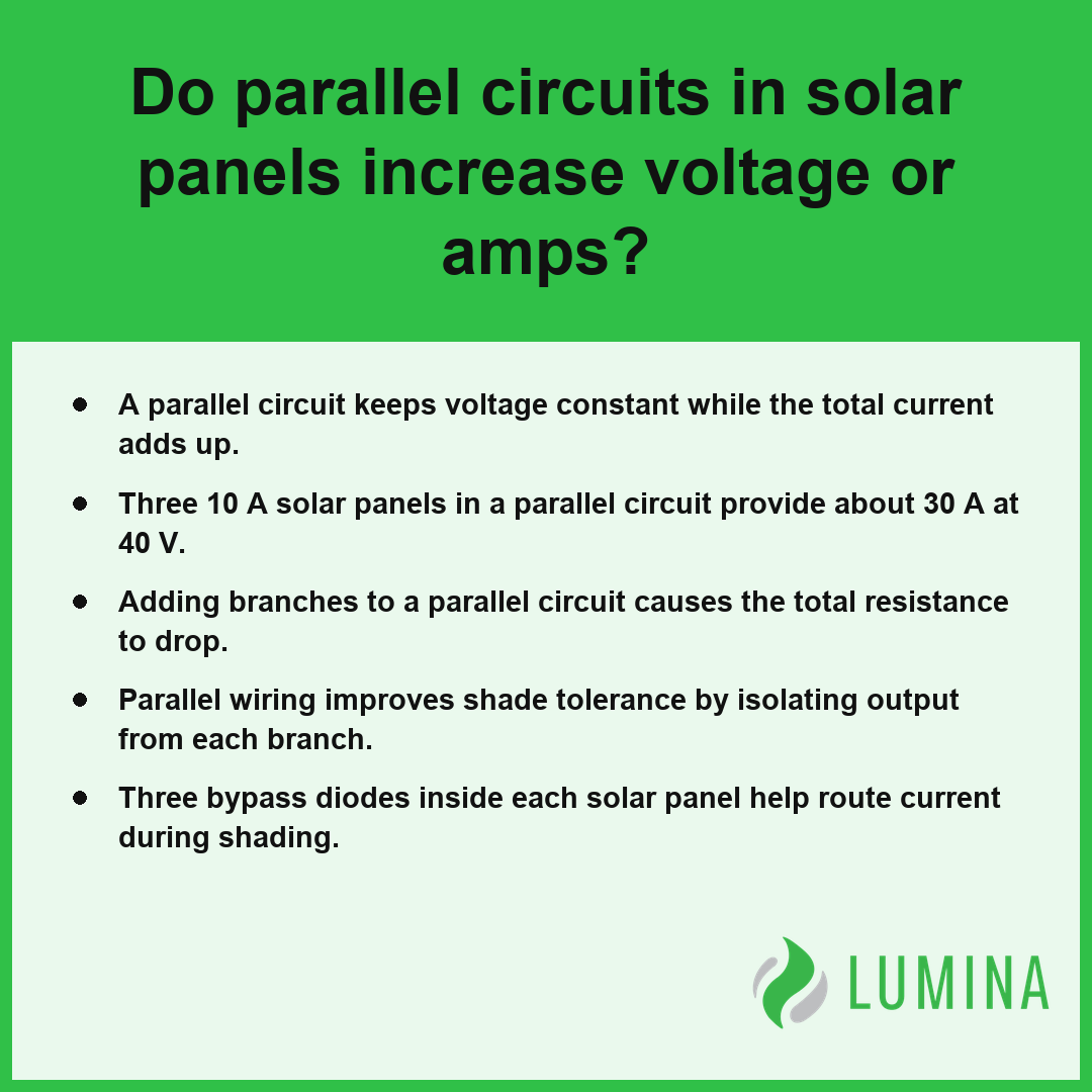
- A parallel circuit keeps voltage constant while the total current adds up.
- Three 10 A solar panels in a parallel circuit provide about 30 A at 40 V.
- Adding branches to a parallel circuit causes the total resistance to drop.
- Parallel wiring improves shade tolerance by isolating output from each branch.
- Three bypass diodes inside each solar panel help route current during shading.
Do Parallel Circuits in Solar Panels Increase Voltage or Amps?
When you connect each solar panel in a parallel circuit, you increase the total current while the open-circuit voltage (Voc) remains the same as that of a single panel.
| Configuration | Panel Count | System Voltage (Vmp/Voc) | Total Current Amperage | Electrical Node Status |
|---|---|---|---|---|
| Single Module | 1 | 32 V | 1x (Base) | Independent |
| Parallel Array | 3 | 32 V | 3x (Additive) | Common/Unified |
Voltage Output Comparison (Parallel Circuit)
How Voltage Stays Constant Across Each Branch
Parallel circuits in solar panels increase total current rather than voltage, as each individual branch maintains the same electrical potential as the others. Per the U.S. Department of Energy, in a parallel arrangement, the current outputs of individual solar modules are additive, which allows the system to maintain a constant voltage level across the entire circuit. Because a parallel circuit connects every component across the same two nodes, the system forces the voltage across each panel to match the voltage of the others. For instance, if you connect three 60-cell residential panels, each with a maximum-power voltage (Vmp) of 30-32 V, the entire array continues to output that same 30-32 V range. This consistency occurs because the nodes at the combiner box act as a single, unified connection point for all positive and negative terminals.
What Happens to Open-Circuit Voltage (Voc) When Panels Differ
- Voltage equality: Every panel must operate at the same voltage dictated by the lowest-performing panel in the group.
- Potential back-feed: If you connect panels with mismatched open-circuit voltage (Voc), the higher-voltage panel may force current into the lower-voltage one, risking damage.
- System stability: Maintaining uniform Voc across all parallel branches is essential to prevent internal currents that reduce overall system efficiency.
Why Does Total Current Add Up Across Branches?
Total current adds up across branches because the current produced by each solar panel flows into the shared output lines, adhering to Kirchhoff’s current law. While the voltage remains restricted to the value of a single unit, the available pathways for electrons increase. As a result, three 10 A panels connected in a parallel circuit provide a total current of about 30 A at the same voltage level.
What Your MPPT Input Limits Mean for Added Branches
When adding branches to increase current, you must ensure the total amperage does not exceed the capacity of your MPPT input. Most residential string inverters have an MPPT input maximum current of about 11-15 A; exceeding this threshold can lead to clipping or equipment failure. Always verify your current totals against the manufacturer’s data sheet before finalizing your parallel connections.
Compare the total calculated current of your final array against the input current limit of your inverter to prevent thermal damage during peak daylight hours.
To ensure system stability and performance when connecting panels in parallel, consider the following technical requirements:- Use a combiner box with appropriately rated overcurrent protection devices (fuses) for each individual branch circuit.
- Ensure the cross-sectional area of the main output cables is sufficient to handle the summed amperage of all connected modules.
- Verify that the charge controller or inverter input is compatible with the total aggregated current of the array.
- Apply locking MC4 connectors or equivalent weatherproof junctions to maintain a secure electrical connection at the common nodes.
How to Calculate Total Current for Three Solar Panels in a Parallel Circuit
Calculating the total current for three solar panels in a parallel circuit involves summing the maximum-power current (Imp) of each individual branch because these parallel circuits force the electricity from each panel to combine into one main flow. When you connect three panels, each with an Imp of 10 A, the resulting total current is about 30 A at the constant voltage produced by a single panel.
| Component Source | Individual Panel Current (Imp) | Cumulative Parallel Output | Recommended Conductor Gauge (AWG) |
|---|---|---|---|
| Solar Panel Array (3 Units) | 10 A | 30 A | 10 AWG |
| Note: Ensure consistent Imp across all modules to maintain system efficiency and safety. | |||
Current Contribution by Solar Panel
- Identify the maximum-power current (Imp) for each individual solar panel by checking the technical specifications label on the back of the module.
- Ensure that each panel in the array has a nearly identical Imp, as any mismatch can cause power losses or efficiency issues within your parallel circuit layout.
- Add the Imp of the first, second, and third panels together (e.g., 10 A + 10 A + 10 A = 30 A) to determine the total current capacity for your wiring path.
- Verify that the combined total current does not exceed the capacity of your cabling; for instance, you will need approximately 10 AWG copper wire to safely handle about 30 A of current at low voltage. According to Occupational Safety and Health Administration, electrical safety standards dictate that the sum of parallel currents must be used to approximate the minimum ampacity rating for circuit conductors and overcurrent protection devices.
- Confirm that your selected combiner box or charge controller can handle the resulting 30 A total, ensuring you have the appropriate string fuse installed if you are connecting three or more strings.
Inspect the rated Ampere capacity of your combiner box terminals to ensure they can accommodate the combined current of your specific panel configuration before finalizing your wiring connections.
Follow these safety and installation precautions when connecting your solar array in parallel:- Install an appropriately rated fuse or circuit breaker on the positive output of each individual solar panel branch to protect against reverse current or short circuits.
- Use polarized MC4 Y-branch connectors that are rated for outdoor exposure and UV resistance to ensure moisture-tight connections.
- Apply a light coating of dielectric grease to connector pins to prevent oxidation and ensure long-term electrical conductivity.
- Secure all wiring runs to the mounting structure using stainless steel cable clips to prevent insulation wear from wind vibration.
Wiring Solar Panels in Parallel: More Power or Just More Current?
Wiring solar panels in parallel circuits increases the total power potential by aggregating the current from each branch while keeping the voltage consistent. Since power is the product of voltage and current, adding a solar panel in a parallel circuit forces your array to produce more total power as long as the voltage remains stable. You are effectively increasing the capacity of the system to push more electrons through the wiring, which allows for higher wattage delivery to your inverter or battery bank. Because total current equals the sum of branch currents, this layout is ideal for systems that need more amperage without exceeding the voltage limits of your charge controller or inverter input.
| Number of Panels | Total Power (W) | Cumulative Current (A) | Required Wire Gauge (AWG) |
|---|---|---|---|
| 1 | 60 | 10 | 14 |
| 2 | 120 | 20 | 12 |
| 3 | 180 | 30 | 10 |
Power Output by Number of Parallel Panels
- Power adds across branches: Ptotal = P1 + P2 + P3…
- Current adds across branches: Itotal = I1 + I2 + I3…
- Voltage remains stable: Vtotal = V1 = V2 = V3…
- Total resistance decreases: 1/Rtotal = 1/R1 + 1/R2 + 1/R3…
When you expand your array using this method, the power output rises linearly with each additional panel added. For instance, if each branch dissipates 60 W at a given voltage, two branches will generate 120 W, and three will generate 180 W. However, this increase in current requires thicker conductors to prevent heat buildup, as transmitting about 30 A at low voltage typically necessitates using 10 AWG copper wire. According to the Institute of Electrical and Electronics Engineers, solar arrays configured in parallel generally require thicker gauge conductors than series connections to account for increased cumulative current, ensuring systems maintain efficiency and adhere to National Electrical Code safety standards for ampacity. You must ensure your combiner box and string fuses are rated to handle this increased flow to prevent overheating at the connection points.
Verify the maximum current rating of your charge controller before adding a new parallel branch to ensure the combined amperage does not exceed your hardware limits.
Series, Parallel, or Series-Parallel Array: Which Layout Fits Your Solar Panels?
Choosing between a series, parallel, or series-parallel array is a functional decision dictated by your solar panel specs and the limitations of your inverter. Selecting the correct layout ensures you maximize energy harvest while keeping voltage and current levels within the safe operational window of your equipment.
| Layout Strategy | Effect on Voltage | Effect on Current | Shade Tolerance |
|---|---|---|---|
| Series | Adds up | Stays constant | Low |
| Parallel | Stays constant | Adds up | High |
| Series-Parallel | Combination | Combination | Moderate |
Wiring in series allows you to reach the higher voltage ranges required by many string inverters, but it suffers significantly if a single solar panel is shaded, as the entire string output drops. By contrast, parallel circuits isolate branches, allowing unaffected panels to continue producing at full capacity even if one branch experiences a drop in light. Per the National Renewable Energy Laboratory, parallel circuit designs are often preferred for residential systems prone to partial shading because the output of a single module is less likely to restrict the total current of the array compared to a series configuration. The series-parallel array acts as a middle ground, often used when you need both higher voltage and higher total current than a single string can provide. Because parallel circuits add branch currents, you must ensure your combiner box and wiring—typically 10 AWG for 30 A loads—can manage the elevated flow. Always verify the maximum input current rating of your specific MPPT input before finalizing your wiring configuration to avoid exceeding component limits.
Compare the maximum open-circuit voltage (Voc) of your string design against the upper voltage threshold listed on your inverter data plate to prevent internal hardware damage.
Consider these additional technical factors when finalizing your solar array design:- Verify that the total open-circuit voltage (Voc) of a series string remains below the maximum input voltage rating of your inverter, even during extreme cold-weather temperature spikes.
- Ensure that the cumulative short-circuit current (Isc) of parallel-connected strings does not exceed the maximum DC input current rating of the inverter’s MPPT channels.
- Calculate voltage drop over long wire runs to ensure efficiency, using thicker gauge wiring for longer distances to minimize energy losses.
- Install bypass diodes in panels if they are not already integrated, as these prevent localized hot spots and current bottlenecks during partial shading events.
Why Total Resistance Drops When You Add Branches to a Parallel Circuit
Total resistance drops when you add branches to a parallel circuit because each new branch provides an additional path for electrical flow, effectively decreasing the overall opposition to current. In a circuit containing multiple resistors, the equivalent resistance is calculated by taking the reciprocal of the sum of the reciprocals of each individual branch resistance. Because each added branch contributes to the total conductive capacity of the system, the final value will always be lower than the resistance of the smallest single branch in the array.
| Number of 10Ω Branches | Conductive Paths | Total Resistance (Ω) | Current Capacity Relative to Single Branch |
|---|---|---|---|
| 1 | 1 | 10.0 | 1x |
| 2 | 2 | 5.0 | 2x |
| 4 | 4 | 2.5 | 4x |
| 5 | 5 | 2.0 | 5x |
| 10 | 10 | 1.0 | 10x |
Total Resistance with Additional 10Ω Parallel Branches
The inverse relationship between the number of branches and total resistance is demonstrated by the following mathematical behaviors:
- Two equal 10 ohm resistors in parallel result in a total resistance of 5 ohms.
- Adding more branches continues to decrease the total resistance, regardless of whether the branches are identical or have varying loads.
- The total resistance is defined by the formula 1/Rtotal = 1/R1 + 1/R2 + …, ensuring that every parallel connection lowers the global resistance of the array.
Per the Department of Energy, adding solar panels in parallel allows the total current of the system to increase while maintaining the voltage of a single panel, effectively serving as an approximation of how the system reduces total electrical resistance to allow for higher power throughput. As you increase the number of parallel strings in your solar setup, consider how the declining total resistance impacts the overall current carrying capacity of your conductors to prevent heat buildup. Verify your system’s total amperage against the rated thermal capacity of your copper wiring to ensure the gauge is sufficient for the combined load.
Consider these practical implications for managing parallel electrical systems:- Power dissipation increases linearly with the number of branches when voltage remains constant.
- Thermal management becomes critical because total heat generation scales with the increased total current.
- Voltage drops across internal wiring become more significant as the total current draw of the parallel network rises.
- Component failure in one branch does not stop current flow through the remaining parallel paths.
Frequently Asked Questions
Is a parallel circuit better than series for solar panels in partial shade?
Yes, a parallel circuit is better for shade because a shaded solar panel reduces only its own branch’s current while other branches maintain full production. In a series string, one shaded solar panel can throttle the output of the entire string, whereas parallel branches utilize a bypass diode to bypass current.
Do I need string fuses when wiring solar panels in a parallel circuit?
You need string fuses when three or more strings share a parallel circuit connection to protect against fault currents, typically sized at 1.56 × Isc. Two parallel strings generally require no fuses if the solar panel’s series fuse rating can tolerate the back-current from the other string.
What wire size do I need for solar panels connected in a parallel circuit carrying 30 amps?
You need about 10 AWG copper wire to safely carry 30 amps at low voltage in a parallel circuit. This gauge helps keep your voltage drop within the recommended 2-3 percent limit, ensuring the efficiency of your solar energy system as you move power from your combiner box.
How many parallel solar strings can one inverter MPPT input handle before it clips?
One inverter MPPT input can generally handle strings up to a maximum of about 11-15 A for typical residential string inverters. Because each parallel string adds to the total current, you must ensure your combined string current does not exceed these specific input limits to avoid performance clipping.
How do you connect batteries in a parallel circuit for a solar system and how many can you join?
You connect batteries in a parallel circuit by linking all positive terminals together and all negative terminals together, which keeps the total voltage equal to a single battery while increasing total current capacity. You can join multiple units as long as the branches have nearly equal voltage to prevent back-feeding.