Series and Parallel Circuits: Current, Voltage, Inverter Limits, Shade Tolerance, Wire Size, Power Output, Temperature Effect, Panel Matching, Fusing
Series and parallel circuits are two ways of wiring solar panels together, either end to end or side by side. Key aspects include voltage, current, shade tolerance, inverter limits, power output, wire size, panel matching, temperature effect, and fusing. When you wire panels in series, their voltages add up while the current stays the same as that of a single panel. When you wire them in parallel, the current adds up while the voltage stays the same. Series strings are more sensitive to shade, because one shaded panel can limit the output of every panel on that string, while parallel connections let each panel contribute more independently. Your inverter has a maximum input voltage and current, so the wiring layout must keep the array within those limits. Solar installers in Washington DC often plan string layouts around roof angles, nearby trees, and inverter specifications. This article explains how voltage, current, shade tolerance, and inverter limits connect to each wiring choice.
Key Takeaways
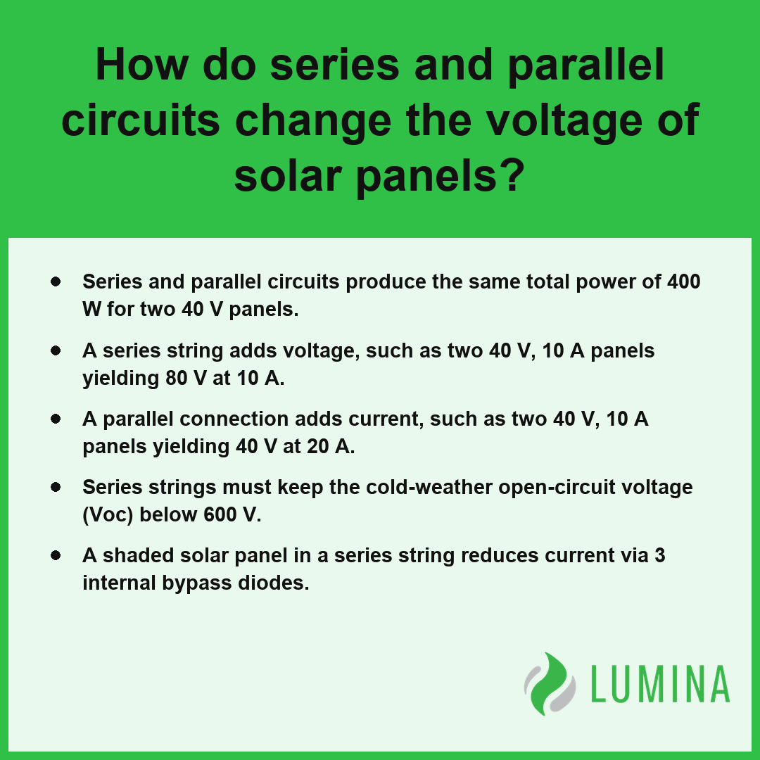
- Series and parallel circuits produce the same total power of 400 W for two 40 V panels.
- A series string adds voltage, such as two 40 V, 10 A panels yielding 80 V at 10 A.
- A parallel connection adds current, such as two 40 V, 10 A panels yielding 40 V at 20 A.
- Series strings must keep the cold-weather open-circuit voltage (Voc) below 600 V.
- A shaded solar panel in a series string reduces current via 3 internal bypass diodes.
How Do Series and Parallel Circuits Change the Voltage of Solar Panels?
When you use series and parallel circuits to configure your solar panels, you change the voltage because a series string sums the open-circuit voltage (Voc) and maximum power voltage (Vmp) of each solar panel, whereas a parallel connection maintains the individual panel voltage while summing the short-circuit current (Isc). Per the Department of Energy, solar installations often use a mix of series and parallel wiring—known as series-parallel arrays—to fine-tune voltage and current levels so they align with the compatibility requirements of specific inverters.
| Configuration Type | Voltage (Voc/Vmp) Behavior | Current (Isc/Imp) Behavior | Primary Design Impact |
|---|---|---|---|
| Series String | Additive (Sum of all panels) | Constant (Matches single panel) | Maximizes DC voltage for inverter compatibility |
| Parallel Connection | Constant (Matches single panel) | Additive (Sum of all panels) | Increases total amperage capacity |
| Series-Parallel Array | Adjustable (Based on string count) | Adjustable (Based on string branches) | Optimizes current/voltage within inverter input limits |
Voltage Output Comparison (Example 40V Panels)
Why a Series String Adds Voltage
Series and parallel circuits change the voltage of solar panels by determining whether the electrical pressure of individual units aggregates or remains constant. In a series string, panels are connected end to end to create a single path for electricity. Because the current remains equal across each component, the open-circuit voltage (Voc) and maximum power voltage (Vmp) of each panel sum together. For example, two 40 V, 10 A panels in series produce 80 V at 10 A.
How Open-Circuit Voltage (Voc) Rises in Cold Weather
You must account for temperature-dependent voltage increases during the design phase. As temperatures drop below 25 °C, the Voc of a solar panel rises by about 0.25 to 0.35% per °C, which can push a series string toward the 600 V maximum input of a typical residential string inverter.
Why a Parallel Connection Keeps Voltage the Same
A parallel connection maintains the voltage of a single panel while aggregating the current across multiple branches. Because the panels connect across the same two nodes, the total voltage of the array stays equal to the voltage of a single panel, while the system current is the sum of the individual branches. For example, two 40 V, 10 A panels in parallel produce 40 V at 20 A.
Does Wiring Change Total Power?
Wiring configuration does not change the total power output for a given set of identical solar panels. Regardless of the arrangement, total power equals the product of the total voltage and total current.
- Series configuration: Two 40 V, 10 A panels yield 400 W.
- Parallel configuration: Two 40 V, 10 A panels yield 400 W.
- Current behavior: Parallel branches add current, necessitating fuses rated at 15 to 20 A in a combiner box.
Verify that the cumulative Voc of your cold-weather string voltage remains safely below the maximum input rating of your inverter.
When designing solar arrays, several critical system-level factors must be considered alongside electrical configurations:- Shading losses are more severe in series strings, as a single obstructed panel can disproportionately reduce the power output of the entire string.
- Voltage temperature coefficients must be calculated to ensure that, on cold mornings, the cumulative open-circuit voltage does not exceed the inverter’s maximum input rating.
- Overcurrent protection devices, such as fuses or circuit breakers, are mandatory when connecting three or more strings in parallel to prevent fire hazards during reverse current faults.
- Wire gauge requirements increase in parallel configurations because the combined amperage necessitates thicker conductors to minimize resistive power loss.
How Wiring Solar Panels in Parallel Adds Current Compared to a Series Circuit
Wiring solar panels in parallel adds current compared to a series circuit by providing multiple paths for electrical flow, which causes the amperage to sum while the voltage remains consistent across all branches. In a series string, the current is restricted to the rating of a single panel, but a parallel connection allows you to combine the short-circuit current (Isc) of multiple panels, which typically ranges from 10 to 14 A per unit. For example, two 40 V, 10 A panels wired in parallel produce 40 V at 20 A, whereas those same panels in a series circuit would yield 80 V at 10 A. By utilizing parallel architecture, you essentially multiply the system’s total current capacity, though this necessitates the use of a combiner box to safely merge these branches, often utilizing fuses rated between 15 and 20 A.
| Configuration | Output Voltage (V) | Output Current (A) | Primary Benefit | Required Protection |
|---|---|---|---|---|
| Parallel (2 Panels) | 40 V | 20 A | High Current Capacity | Combiner Box with 15–20A Fuses |
| Series (2 Panels) | 80 V | 10 A | Higher System Voltage | Standard DC Disconnect |
Electrical Output: Parallel vs. Series (2 Panels)
- Parallel output: Sums current while maintaining the voltage of a single panel.
- Series string output: Sums voltage while maintaining the current of a single panel.
- Component requirement: Parallel circuits often require thicker wire to handle the increased amperage safely.
- System protection: Parallel branches necessitate fuses or breakers within a combiner box to manage the combined current.
When you evaluate the electrical design of series and parallel circuits, you must verify that your chosen wire gauge can support the increased current resulting from parallel branches without causing significant resistive heat buildup. Per American National Standards Institute, residential solar array designs must approximate compliance by ensuring that the total system current never exceeds the specific amperage ratings of the installed conductors or the overcurrent protection devices.
Consider these technical considerations when implementing parallel solar configurations:- Use thicker gauge wiring to account for the increased amperage and minimize voltage drop across the system.
- Ensure all connected panels have identical voltage specifications to prevent reverse current flow and efficiency losses.
- Install blocking diodes if panels are prone to significant shading to protect individual strings from power drain.
- Verify that the charge controller input limits are compatible with the higher total current produced by the parallel array.
How Many Solar Panels Can Go in One Series String Without Exceeding the Inverter’s Maximum Voltage
You determine how many solar panels can go in one series string without exceeding the inverter’s maximum voltage by calculating the cumulative open-circuit voltage (Voc) of the panels at the coldest expected site temperature and ensuring the sum remains below the equipment’s rated input ceiling. Per National Electrical Code, the total voltage of a series string of solar modules should be calculated using the module manufacturer’s maximum voltage rating adjusted for the lowest expected ambient temperature in the installation region. While series and parallel circuits offer flexibility, the voltage limit is rigid because exceeding it can cause permanent damage to your string inverter. Since the open-circuit voltage (Voc) rises by about 0.25 to 0.35% per °C below 25 °C, you must account for this cold-weather increase to prevent the array from outputting dangerous voltages during winter mornings.
| Parameter | Specification / Logic | Operational Role |
|---|---|---|
| Maximum DC Input Voltage | 600 V (Typical Residential) | Hard ceiling to prevent catastrophic inverter failure. |
| Temperature Coefficient | 0.25% to 0.35% per °C | Factor for calculating Voc rise in cold-weather conditions. |
| Minimum Startup Voltage | 150 V | Required Vmp threshold to initiate power conversion. |
| String Sizing Constraint | (Max Inverter Input) / (Adjusted Cold Voc) | Determines the maximum safe module count per string. |
Example System Voltage Thresholds (Volts)
- Maximum Input Voltage: Typically 600 V for common residential systems, which defines the absolute safety threshold for your string.
- Temperature Coefficient Adjustment: You must multiply the Voc by the expected temperature drop below 25 °C to find the “cold” voltage of a panel.
- String Count Calculation: Divide the inverter’s maximum input voltage by the adjusted cold-weather Voc of a single panel, then round down to the nearest whole number.
- Minimum Startup Voltage: Ensure the total Vmp of the string stays above the inverter’s startup threshold, often 80 to 150 V, to allow the system to initiate power production.
Verify your panel’s cold-weather Voc datasheet specifications against the local extreme low temperature to ensure your string length does not push the system past the 600 V safety limit.
Follow these practical steps to perform an accurate cold-weather string sizing calculation:- Locate the record low temperature for your installation site using ASHRAE design data or historical meteorological records.
- Identify the temperature coefficient of Voc from the solar module datasheet, typically expressed as a negative percentage.
- Calculate the voltage increase factor by multiplying the temperature difference from 25°C by the module’s voltage coefficient.
- Apply the voltage correction factor to the module’s standard test condition (STC) Voc to determine the worst-case voltage per panel.
- Divide the inverter’s maximum input voltage by this adjusted Voc value and round down to the nearest whole number to determine the maximum panels per string.
What Happens If One Solar Panel Is Shaded in a Series Circuit Versus a Parallel Circuit
What happens if one solar panel is shaded in a series circuit versus a parallel circuit depends on how the current flow is restricted by the architecture of the series and parallel circuits. In a series string, the current is limited by the weakest panel, whereas in a parallel connection, each branch operates independently, preventing a single shaded panel from throttling the entire array’s performance. According to the National Institute of Standards and Technology, mismatch losses in series-connected photovoltaic systems occur because the current in each cell or module must be identical, which makes the weakest or most shaded component the primary limiting factor for the entire string.
Typical Short Circuit Current (Isc) Range
| Feature | Series String Impact | Parallel Connection Impact |
|---|---|---|
| Current Flow | Reduced to the level of the shaded panel | Remains unaffected for non-shaded strings |
| Voltage Impact | Bypass diodes activate to remove the shaded segment | Voltage remains stable across the branch |
| Total Output | Significant drop across the entire string | Only the shaded branch experiences a drop |
When you use a series string, the system relies on the 3 bypass diodes typically found in each solar panel to route current around shaded cells, yet the overall current is still forced to the lowest common denominator. Conversely, a parallel connection allows unshaded strings to continue producing at their maximum potential current (Isc), usually 10 to 14 A, without being pulled down by the poor performance of a shaded counterpart. While parallel setups provide better shade tolerance, they require careful monitoring of current levels to ensure that the total output does not exceed the capacity of the combiner box fuses, typically rated for 15 to 20 A. Evaluate the projected shade patterns across your roof space to determine if the wiring complexity of a parallel arrangement is necessary to protect your total energy harvest.
To mitigate performance losses from shading, consider these architectural strategies for your solar array:- Incorporate module-level power electronics, such as microinverters or DC optimizers, to allow each panel to operate at its individual maximum power point.
- Design string layouts to group modules with similar solar exposure profiles to minimize cross-string performance degradation.
- Utilize rapid shutdown hardware that inherently isolates shaded sections to maintain overall system safety and voltage stability.
- Install panels in an orientation that minimizes the duration of shadow movement across the array surface throughout the day.
How Microinverters and Power Optimizers Change the Series Versus Parallel Choice for Solar Panels
Microinverters and power optimizers change the series and parallel circuits choice by decoupling individual solar panel output from the rest of the array, effectively creating a hybrid system architecture. While traditional installations rely on a string inverter to handle long series strings of panels, microinverters are mounted directly behind each solar panel to convert DC to AC at the module level. Similarly, power optimizers are installed at each panel to track the maximum power point and condition the voltage before sending it to a central inverter. These technologies mitigate the limitations inherent in basic series connections, such as the drop in output caused by shade or mismatched panels. Per the Institute of Electrical and Electronics Engineers, module-level power electronics enable individual solar panels within a series-wired array to function at their own maximum power point, which helps offset power losses often triggered by module mismatch or partial shading.
| Technology | Primary Function | Impact on Wiring |
|---|---|---|
| Microinverter | Converts DC to AC at the panel | Removes the need for high-voltage DC string wiring |
| Power Optimizer | Adjusts DC voltage and current | Allows series strings to maintain high performance under shading |
By implementing these module-level electronics, you bypass the performance penalties typical of standard series wiring, as each panel operates independently rather than being forced to share a common current. This allows for more flexible array designs on roofs with complex orientations or partial obstructions. Evaluate the specific module-level monitoring capabilities of your chosen hardware to determine if the increased equipment cost is justified by the expected gain in energy harvest at your site.
These module-level technologies offer additional architectural advantages for residential and commercial solar installations:- Enhanced system monitoring capabilities allow for real-time performance tracking of every individual solar panel.
- Improved fire safety protocols are achievable through rapid shutdown functionality, which de-energizes the high-voltage DC lines at the module level.
- Easier system scalability enables homeowners to add more solar panels to the array at a later date without replacing existing inverter hardware.
- Increased roof layout flexibility permits the installation of panels across multiple roof facets with different orientations and tilt angles.
Frequently Asked Questions
Do series and parallel solar panel wiring produce the same total watts?
Yes, series and parallel solar panel wiring produce the same total power, as both configurations yield 400 W of output using two identical panels. While a series string doubles voltage to 80 V at 10 A, a parallel connection doubles current to 40 V at 20 A, keeping total wattage identical.
Does wiring solar panels in series let you use thinner wire on long cable runs?
Yes, wiring solar panels in series allows for the use of thinner wire because higher voltage reduces resistive losses. By raising voltage through a series string, you decrease the current required to transmit the same power, which minimizes heat loss across long cable runs compared to low-voltage, high-current parallel connections.
Can you mix different solar panel models in a series or parallel circuit?
No, you should not mix different solar panel models because mismatches waste output. In a series string, you must match current ratings to prevent the lowest-rated panel from limiting the entire string. In a parallel connection, you must match voltage ratings to ensure efficient energy production across all branches.
Why does cold weather matter when wiring solar panels in series?
Cold weather matters in series wiring because the open-circuit voltage (Voc) rises by about 0.25 to 0.35% per °C below 25 °C. You must ensure the cold-weather Voc of your string remains below the inverter’s maximum input voltage, which is typically 600 V for residential systems.
Do parallel solar panel strings need fuses or a combiner box, and when?
Yes, you need a combiner box with fuses typically rated for 15 to 20 A when three or more strings are connected via a parallel connection. Fuses protect the electrical components from overcurrent, ensuring safe performance when managing power distribution between series and parallel circuits.