
Voltmeter: Safety Category, Voltage Rating, Connection Method, Expected Readings, Price, Types, Input Impedance, Solar Uses, Limitations, Accuracy
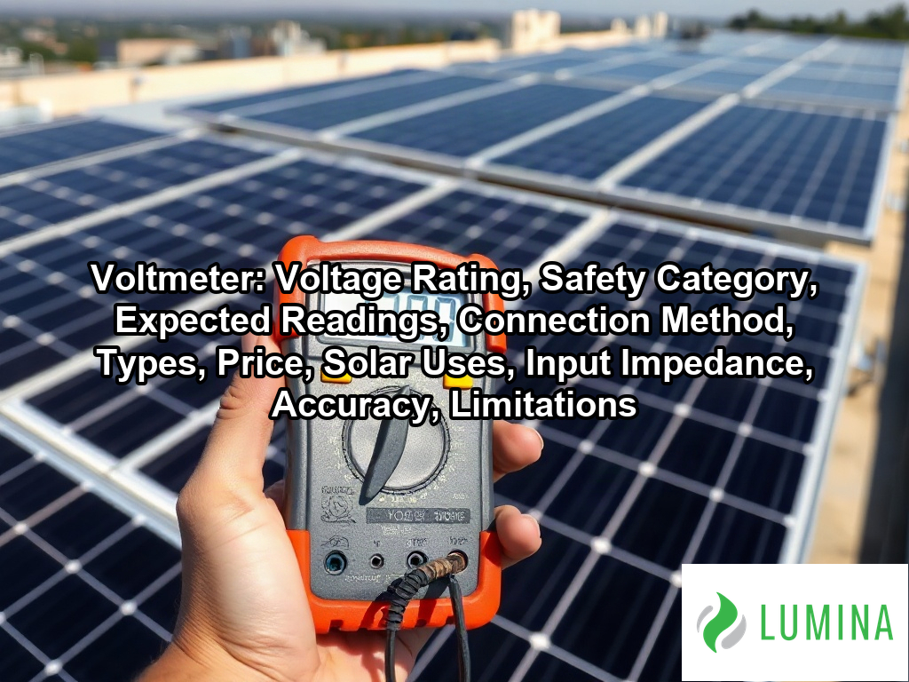
A voltmeter is an electrical instrument that measures the potential difference between two points in a circuit, displayed in volts. Key aspects include voltage rating, safety category, expected readings, connection method, types, price, solar uses, input impedance, accuracy, and limitations. You connect it in parallel across the component you want to test, such as a solar panel’s output terminals, so it draws very little current and reads the voltage accurately. In a solar array, it lets you confirm that a panel, string, or battery bank is producing the voltage the system was designed for. Technicians at solar companies in Washington DC use it routinely to check open-circuit voltage, trace faults, and verify wiring before commissioning. This article explains the correct connection method, the voltage rating your meter needs, the safety category that suits high-voltage DC work, the main types available, and the readings you can expect from healthy panels.
Key Takeaways
- Connect your voltmeter in a parallel connection, never in a series configuration.
- A digital multimeter should have about 10 megaohms (10 MΩ) input impedance.
- Open-circuit voltage (Voc) rises by 0.25% to 0.35% per °C as temperatures drop.
- Use a CAT III 600 V or 1,000 V rated tool for work on a combiner box or inverter.
- Residential strings often reach 300 to 600 V DC, with 600 V DC as the general limit.
Do You Connect a Voltmeter in Series or Parallel When Testing a Solar Panel?
Yes, you connect a voltmeter in parallel when testing a solar panel, as this arrangement allows the device to sample electric potential difference without interrupting the flow of current. By placing the test leads directly across the positive and negative output terminals, you measure the voltage across the component while the circuit remains intact. This method relies on the high input impedance of the instrument—typically about 10 megaohms (10 MΩ) for a standard digital multimeter—which ensures the device draws only microamps of current, effectively eliminating the risk of loading down the source or introducing significant measurement error.
| Measurement Parameter | Technical Specification | Operational Rationale |
|---|---|---|
| Meter Input Impedance | 10 MΩ (Typical) | Prevents parasitic loading; minimizes current draw. |
| Connection Topology | Parallel Configuration | Maintains circuit integrity; prevents internal meter damage. |
| Field Instrument Accuracy | ±0.5% to ±1.0% DC | Ensures reliable voltage readings in variable field conditions. |
Basic DC Accuracy of Field-Grade Instruments
When performing these measurements, keep the following technical characteristics of your testing equipment in mind:
- Input Impedance: Maintaining a high input impedance of 10 megaohms (10 MΩ) prevents the voltmeter from acting as a parasitic load on the solar panel.
- Connection Geometry: Always maintain a parallel connection, as placing the instrument in series would require you to break the circuit path and force all current through the meter, potentially damaging internal components. Per National Renewable Energy Laboratory, measuring the open-circuit voltage of a photovoltaic module requires a parallel connection across the positive and negative output leads while the panel is disconnected from its normal load.
- Accuracy Requirements: Field-grade instruments typically offer a basic DC accuracy of ±0.5% to ±1% of reading, which is sufficient for verifying the open-circuit voltage (Voc) or maximum power voltage (Vmp) of a module.
- Signal Processing: Digital models utilize an analog-to-digital converter to display values, whereas older analog moving-coil versions rely on a galvanometer and internal resistors to physically move a needle.
Verify that your test leads are securely seated in the multimeter ports labeled for voltage before touching them to the solar panel terminals.
Ensure your multimeter is properly configured for these field measurements by adhering to the following safety and procedural guidelines:- Set the dial to the DC voltage (VDC) mode before making contact with the panel terminals to prevent potential short-circuiting.
- Verify that your test leads are plugged into the correct “COM” and “V” ports on your multimeter.
- Ensure all exposed metal connectors on the test leads are insulated, except for the probe tips, to avoid accidental bridging of the terminals.
- Conduct tests under stable irradiance conditions to minimize fluctuations in the open-circuit voltage reading.
What Voltage Should a Healthy Solar Panel Show on a Voltmeter, and Why Is It Higher on Cold Mornings?
You should expect a typical 60- or 72-cell solar panel to show an open-circuit voltage (Voc) between 30 and 50 V DC on your voltmeter, a value that increases by approximately 0.25% to 0.35% for every degree Celsius drop in temperature because cold conditions enhance the semiconductor’s ability to maintain a higher potential difference.
Typical Voc Range for Solar Panels (V DC)
Open-Circuit Voltage (Voc) Readings on a Single Solar Panel
A healthy solar panel typically shows an open-circuit voltage (Voc) between 30 to 50 V on your voltmeter when measured under sunlight. While this reading confirms the panel is generating potential, it does not verify the panel can deliver its full power output. You should cross-reference your findings with the nameplate data on the back of the module, as a good Voc reading simply proves the internal circuits are intact.
Why Is Voltage Higher in Cold Weather?
The voltage on a solar panel is higher in cold weather because the semiconductor properties of silicon are temperature-dependent. Per the International Electrotechnical Commission, the temperature coefficient of voltage for standard crystalline silicon modules is negative, meaning the voltage output increases by a defined percentage for every degree Celsius decrease below the standard test condition of 25 degrees Celsius. As the internal temperature of the cell drops, the open-circuit voltage (Voc) rises by roughly 0.25% to 0.35% per °C. This physical reaction ensures that cold, sunny mornings often produce the highest voltage readings of the entire year.
Checking a Full String Against Temperature-Adjusted Voc
When you measure a series-connected string, the individual voltages of each solar panel accumulate, often reaching 300 to 600 V DC. Use this table to understand how ambient temperature influences your expected voltmeter readings:
| Temperature Condition | Effect on Voc |
|---|---|
| Rising Temperature | Voltage decreases |
| Falling Temperature | Voltage increases |
| Standard Test Conditions | Baseline voltage at 25 °C |
Battery Bank Readings at 12, 24 or 48 V
A voltmeter is also used to verify the state of charge for battery banks, which are configured at standard nominal voltages of 12, 24 or 48 V. Unlike a solar panel, which displays Voc, a battery bank will show a fluctuating voltage level that indicates how much energy remains stored. If you are troubleshooting a system, always confirm that your battery bank voltage matches the inverter input specifications before enabling the main power switch.
Compare your measured Voc against the temperature-corrected values provided in the panel manufacturer’s technical data sheet to ensure the string voltage remains within safe operating limits for your equipment.
Follow these safety and diagnostic procedures when measuring your solar panel’s voltage:- Ensure your multimeter is set to the DC voltage mode and rated for at least 600V to accommodate potential surges.
- Always disconnect the solar panel from the charge controller or inverter before testing to avoid damaging your equipment.
- Use insulated alligator clips to maintain a steady connection to the MC4 connectors, as hand-holding probes can lead to inconsistent readings or arc risks.
- Avoid measuring voltage during low-light or shaded conditions, as the resulting reading will be significantly lower than the expected Voc.
- Check the MC4 connectors for signs of heat damage, oxidation, or loose wiring if your Voc reading fluctuates or appears unusually low.
What DC Voltage Rating Does a Voltmeter Need to Be Safe on a Home Solar Array?
To safely work on a home solar array, a voltmeter must possess a maximum DC voltage rating that exceeds the highest potential voltage generated by the entire string or battery bank you intend to test. Because residential solar strings often reach 300 to 600 V DC, with 600 V DC serving as the general maximum for one- and two-family dwellings, your tool must be capable of handling these high levels of electrical potential without failing or risking an internal short circuit.
| System Classification | Maximum Operating Voltage (Voc) | Recommended Meter Rating | Safety Margin Requirement |
|---|---|---|---|
| Standard Residential | Up to 500 V DC | 600 V DC | Minimum 20% over Voc |
| High-Capacity / Commercial | Up to 800 V DC | 1,000 V DC | Minimum 20% over Voc |
Recommended Voltmeter DC Rating (Volts)
- System Voltage Headroom: Ensure the meter’s maximum DC rating is at least 20% higher than the calculated maximum open-circuit voltage (Voc) of the string to account for potential cold-weather voltage spikes. According to the National Electrical Manufacturers Association, digital multimeters used for testing DC solar installations should be rated for the maximum system voltage plus a safety margin to prevent internal arc flash hazards during the measurement of open-circuit voltage.
- Standard Residential Ranges: Choose a voltmeter rated for at least 600 V DC, as this covers standard residential strings and common 12, 24, or 48 V battery bank configurations.
- High-Capacity Requirements: Select meters rated for 1,000 V DC if you are servicing larger systems that approach or exceed the 600 V DC limit for dwellings.
- Equipment Compatibility: Verify the CAT rating matches the physical location of your test, such as using a CAT III 600 V or 1,000 V rated tool for work within a combiner box.
Inspect the insulation on your test leads for any nicks or exposure before connecting them to a high-voltage string to ensure the entire assembly maintains its safety rating during the measurement.
Follow these best practices when selecting and maintaining a voltmeter for solar applications:- Verify the meter is CAT III or CAT IV rated to ensure it can withstand the transient voltage surges common in electrical service entrance environments.
- Inspect test leads for cracked insulation or exposed copper before every measurement, as high-voltage DC current can sustain an arc if wires are damaged.
- Utilize insulated crocodile clips to maintain a secure connection, reducing the risk of accidental slippage while measuring live solar strings.
- Confirm the meter’s internal fuse is rated for high-energy DC circuits to prevent catastrophic failure if an incorrect setting or short circuit occurs.
Is a CAT III 600 V or 1,000 V Voltmeter Required for Working on Combiner Boxes and Inverters?
Yes, a CAT III 600 V or 1,000 V voltmeter is required for working on combiner boxes and inverters because these components handle high-energy circuits where dangerous transient voltage spikes can occur. Per the American National Standards Institute, the ANSI/ISA-61010-1 standard generally specifies that CAT III equipment is necessary for measurements within building installations, such as distribution panels and branch circuits, where high-energy transients are a possibility. While residential solar strings often reach 300 to 600 V DC, the unpredictable nature of electrical faults within an inverter or a crowded combiner box necessitates equipment that has been tested to withstand severe electrical surges. Using a meter with the correct CAT rating ensures that the internal components of the device are physically protected from arching or internal shorting if a voltage surge happens while you are taking a measurement.
| Application Environment | Minimum CAT Rating | Max Voltage Threshold | Primary Risk Factor |
|---|---|---|---|
| Residential Combiner Boxes | CAT III | 600 V | High-energy transient spikes |
| Large-Scale Inverter Arrays | CAT III | 1,000 V | Internal electrical fault arcing |
| Utility Service Entrance | CAT IV | Variable | High-current surge potential |
Voltage Rating Comparison (Volts)
When selecting a tool for these specific tasks, you must verify the rating clearly marked on the casing of your digital multimeter:
- CAT III 600 V: Suitable for testing circuits connected directly to the distribution part of the building, including most residential combiner boxes.
- CAT III 1,000 V: Recommended for larger arrays or systems where the voltage may approach the upper limits of residential standards.
- CAT IV: Required only if you are measuring at the primary power service entrance or the utility connection point.
Always inspect the physical condition of your test leads and ensure they carry the same CAT rating as the voltmeter before probing any live electrical connections inside an inverter cabinet.
To ensure your test equipment remains safe and functional, consider these best practices:- Inspect test leads for cracked insulation or exposed copper before every measurement.
- Confirm that the meter’s fuse is rated for the specific high-interrupting capacity (HRC) required by the CAT rating.
- Ensure the meter is calibrated annually to maintain the accuracy and safety parameters defined by the manufacturer.
- Use only factory-supplied accessories, as generic aftermarket leads often lack the necessary physical creepage and clearance distances for high-voltage ratings.
Analog or Digital: Which Voltmeter Should You Use for Solar Panel Testing?
A digital multimeter is the standard tool for solar panel testing, while an analog voltmeter is largely obsolete for modern field applications. Modern digital devices provide the precision and high input impedance required for accurate solar diagnostics, whereas analog units rely on physical needle movements that are prone to mechanical error and lower sensitivity.
Typical Input Impedance (Ohms)
| Feature | Digital Multimeter | Analog Voltmeter |
|---|---|---|
| Input Impedance | About 10 megaohms (10 MΩ) | 1,000 to 20,000 Ω/V |
| Display | LCD (3.5 to 6.5 digits) | Moving-coil needle |
| Field Accuracy | ±0.5% to ±1% of reading | Depends on needle parallax |
| Power Source | Internal battery | None required for voltage |
You should prioritize a digital multimeter because its 10 MΩ input impedance ensures the voltmeter does not draw enough current to load the circuit, preventing distorted readings of the open-circuit voltage (Voc) or maximum power voltage (Vmp). According to National Institute of Standards and Technology, digital multimeters offer superior input impedance compared to analog meters, which helps minimize circuit loading and enhances measurement accuracy when testing high-impedance photovoltaic systems. While analog meters are robust, their low sensitivity can cause them to drain too much current from small power sources, leading to inaccurate results during your testing process. Always verify that your digital multimeter’s display remains stable and easy to read under direct sunlight conditions before confirming your measurements.
When selecting and using your testing equipment, follow these best practices for optimal results:- Use silicone-insulated test leads rated for the maximum voltage and Category (CAT) rating of your solar array.
- Inspect test lead probes for damage or frayed insulation before every measurement to prevent arcing.
- Ensure your multimeter is set to the correct DC voltage range higher than the expected open-circuit voltage (Voc) to avoid internal fuse failure.
- Confirm that the meter’s battery is fully charged, as low power can cause drift in digital signal processing.
- Clean the solar panel surface before testing to ensure uniform irradiance and accurate voltage readings.
Frequently Asked Questions
Does a voltmeter’s 10 megaohm input impedance affect solar panel readings?
A voltmeter’s 10 megaohm input impedance does not significantly affect solar panel readings because the high impedance ensures the device draws only microamps of current. By maintaining this high input impedance, a digital multimeter samples voltage without placing a significant load on the solar panel or the circuit being measured.
How accurate is a voltmeter for solar work and how often should it be calibrated?
A voltmeter used for solar work provides a typical basic DC accuracy of ±0.5% to ±1% of the reading for standard field models. While the research specifies these accuracy levels for a digital multimeter, it does not provide a specific universal interval for recalibration frequency to maintain those performance standards.
How much does a solar-rated voltmeter or multimeter cost?
A solar-rated handheld digital multimeter generally costs between $50 and $300 for CAT III or CAT IV rated models suitable for field use. While basic units start at $20, professional bench-grade equipment can cost $500 or more depending on the required precision and the necessary safety features for high-voltage work.
How do I use a voltmeter to confirm a solar string is de-energized or find a bad connector?
You use a voltmeter to confirm a solar string is de-energized by testing the circuit to ensure no voltage is present after disconnection. To find a bad connector or failed panel, you measure the open-circuit voltage (Voc) across segments to identify where the electrical continuity is broken within the string.
Can a voltmeter tell me if my solar panel is producing full power?
No, a voltmeter cannot tell you if your solar panel is producing full power because it only measures electrical potential and cannot detect current or calculate wattage. To determine if a panel is functional, you must use a clamp meter to measure current and then multiply it by the voltmeter reading.