
Crystalline Silicon: Efficiency, Types, Cell Architecture, Lifespan, Price, Heat Tolerance, Manufacturing, Power Output, Limits and Alternatives, Physical Properties
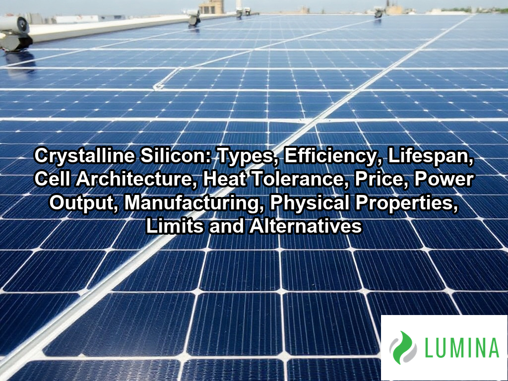
In this guide to “crystalline silicon”, we’ll cover types, efficiency, lifespan, cell architecture, heat tolerance, price, power output, manufacturing, physical properties, and limits and alternatives. When sunlight strikes a wafer, its energy frees electrons inside the silicon, and the cell’s internal electric field pushes them into a current that metal contacts collect. This material forms the core of most modern solar panels VA systems and of the great majority of panels sold worldwide. The article explains the main types, including monocrystalline and polycrystalline, and how each affects the efficiency you can expect. It also covers cell architecture, such as PERC and heterojunction designs, along with typical lifespan and how heat changes the output you receive on hot days.
Key Takeaways
- Crystalline silicon solar modules typically reach 20-24% commercial module efficiency.
- You can expect a typical annual degradation rate of 0.25-0.8% for your solar panels.
- Monocrystalline silicon is currently the standard for high-performance solar modules.
- Crystalline silicon has a band gap of about 1.12 eV at room temperature.
- Power loss for crystalline silicon is -0.25 to -0.40% per °C above 25 °C.
What Is the Difference Between Monocrystalline and Multicrystalline Crystalline Silicon Solar Panels?
The difference between monocrystalline and multicrystalline crystalline silicon solar panels lies primarily in the atomic arrangement within the wafers and the resulting manufacturing efficiency. Monocrystalline silicon consists of a single continuous crystal structure, whereas multicrystalline silicon is composed of many individual grains fused together during the casting of ingots.
Silicon Wafer Thickness (Micrometers)
How Monocrystalline Silicon Is Made and Where It Performs Best
Monocrystalline silicon is produced using the Czochralski process, where a seed crystal is pulled from molten silicon heated to approximately 1,414 °C. This method creates a high-purity, cylindrical ingot that is subsequently squared off and sliced into wafers about 150-180 micrometers thick. Because of the uniform lattice structure, these panels generally provide higher performance in limited space.
Why the Wafer Shape Looks Different in Each Type
- Monocrystalline: Exhibits a uniform dark color and squared corners with chamfered edges due to the cutting process from cylindrical ingots.
- Multicrystalline: Displays a mosaic-like pattern of visible crystalline grains with a blueish, variegated hue resulting from the cooling of molten material in a mold.
How Multicrystalline Silicon Differs in Cost and Output
Multicrystalline silicon involves casting molten material directly into square molds, which reduces energy consumption and waste compared to the Czochralski method. Per the United States Department of Energy, while monocrystalline panels are typically chosen for their superior power density in restricted spaces, multicrystalline options persist in the market as a common alternative due to the lower production costs inherent in their casting process. This manufacturing technique introduces grain boundaries that act as defects, hindering electron flow and leading to lower module efficiency compared to the monocrystalline alternative.
Which Type Fits Your Roof?
| Feature | Monocrystalline | Multicrystalline |
|---|---|---|
| Crystal Structure | Single continuous lattice | Multiple grains |
| Space Efficiency | High | Lower |
Compare the available square footage of your roof against the output density of each panel type to determine if a more efficient monocrystalline system justifies the potential cost difference.
The following factors influence the operational longevity and environmental impact of these solar technologies:- Monocrystalline panels typically offer longer product warranties due to higher structural integrity and fewer internal grain boundaries.
- Multicrystalline panels feature a lower energy payback time during manufacturing because the casting process requires less intensive heating cycles.
- Thermal degradation rates vary between the two, with monocrystalline silicon generally demonstrating superior resistance to temperature-induced performance losses.
What Efficiency Do Crystalline Silicon Solar Panels Reach, and Why Does It Matter for Power per Square Foot?
The efficiency of crystalline silicon solar panels typically ranges from 20-24%, a figure that directly dictates the amount of electrical power you can generate from a limited surface area. Because crystalline silicon acts as an indirect band gap material with a room-temperature band gap of about 1.12 eV, it requires a relatively thick layer of material—typically wafers of 150-180 micrometers—to effectively absorb incident light. While laboratory-scale cells have demonstrated higher performance, commercial modules are constrained by optical losses and the physics of the p-n junction, approaching a practical single-junction efficiency limit of about 29.4%. Per the National Renewable Energy Laboratory, the theoretical maximum efficiency for such cells is established by the Shockley-Queisser limit at approximately 33.7%, providing an upper constraint on how much power can be extracted from a given surface area.
Solar Module Efficiency Comparison
Higher module efficiency is critical if you have limited roof space, as it increases the power density of your solar array. When you select panels with higher efficiency ratings, you maximize the wattage produced per square foot, which allows for a smaller total system footprint. The following table illustrates the relationship between module efficiency and space requirements for a standardized installation footprint:
| Efficiency Category | Typical Module Efficiency | Power Density Impact |
|---|---|---|
| Standard Commercial | 20% | Baseline power per square foot |
| High-Performance | 22% | 10% increase in power per square foot |
| Premium/Best-in-Class | 24% | 20% increase in power per square foot |
Compare the manufacturer’s specified efficiency rating against your total available unshaded roof area to determine if high-efficiency modules justify their higher cost per watt.
Considering the physical constraints of silicon, homeowners should prioritize the following factors when optimizing for limited installation areas:- Assess your roof’s total usable surface area to determine the maximum physical footprint available for panels.
- Prioritize panels with high temperature coefficients, as high-efficiency cells can lose performance in extreme heat.
- Account for local shading patterns, which can disproportionately impact the output of high-density arrays.
- Evaluate the degradation rate of premium panels to ensure the long-term power density remains higher than budget alternatives.
Is TOPCon, HJT, or PERC the Better Crystalline Silicon Solar Cell Technology?
The choice between PERC, TOPCon, and HJT represents the evolution of crystalline silicon solar cell architecture, with each technology offering distinct advantages for electron capture and internal resistance reduction.
Theoretical Efficiency Limits
| Technology | Design Feature | Performance Strength |
|---|---|---|
| PERC | Passivated Emitter and Rear Cell | Mature, cost-effective standard |
| TOPCon | Tunnel Oxide Passivated Contact | High bifaciality and efficiency |
| HJT | Heterojunction Technology | Superior temperature resistance |
PERC remains the widely deployed standard, adding a reflective layer to the rear of the crystalline silicon to bounce unabsorbed photons back into the cell. However, TOPCon has emerged as the successor by utilizing a thin tunneling oxide layer to minimize recombination losses, pushing commercial module efficiency toward the higher end of the 20-24% range. Per the International Technology Roadmap for Photovoltaic, the Tunnel Oxide Passivated Contact architecture provides higher theoretical efficiency limits and improved performance during low-light conditions when compared to standard PERC designs. Meanwhile, HJT layers amorphous silicon onto the crystalline silicon wafer to form a heterojunction, which significantly reduces internal current leakage and offers a lower temperature coefficient than the other designs. While the practical single-junction efficiency limit for crystalline silicon stands at about 29.4%, these architectures serve as the primary pathways to approaching that threshold by optimizing the p-n junction interface. Compare the specific temperature coefficient data on product datasheets to determine if your local climate benefits more from the thermal stability of HJT or the high-output density of TOPCon designs.
Key technical considerations for implementing these solar architectures include the following:- Manufacturing Compatibility: PERC lines can be upgraded to TOPCon with relatively minor equipment modifications, whereas HJT requires entirely new production facility layouts.
- Degradation Rates: HJT exhibits lower Light-Induced Degradation (LID) compared to standard PERC cells due to the inherent properties of amorphous silicon layers.
- Bifacial Potential: Both TOPCon and HJT facilitate higher bifaciality factors than PERC, allowing for greater energy harvesting from reflected ground light.
- Material Intensity: HJT designs often require higher silver consumption, which impacts the overall cost-per-watt profile compared to the more lean-material TOPCon process.
How Long Do Crystalline Silicon Solar Panels Last and How Fast Do They Degrade?
Crystalline silicon solar panels typically last for 25 to 30 years, experiencing a standard annual degradation rate of 0.25-0.8% per year. This loss in performance occurs because the materials within the solar cell slowly respond to environmental stresses, including ultraviolet exposure and cyclical temperature changes, which gradually reduce the ability of the p-n junction to efficiently move electrons. While the panels will continue to produce electricity well beyond their rated service life, their output will decrease year over year. According to Lawrence Berkeley National Laboratory, the vast majority of crystalline silicon photovoltaic systems in the United States continue to produce electricity effectively beyond their initial 20 to 25-year manufacturer power output warranties.
| Degradation Mechanism | Primary Root Cause | Impact on Performance |
|---|---|---|
| Light-Induced Degradation | Boron-oxygen reaction in p-type silicon | Early-stage permanent output drop |
| Mechanical Stress | Cyclical thermal expansion and contraction | Micro-crack development limiting electron flow |
| Environmental Sealing Failure | Moisture ingress through backsheet/encapsulant | Corrosion of metallic conductive contacts |
| Cell Architecture | Doping configuration (n-type vs p-type) | Variation in resistance to impurity-based decline |
Annual Degradation Rate of Crystalline Silicon Panels
Several factors contribute to the speed at which crystalline silicon modules lose their capacity to generate power:
- Light-Induced Degradation: Reactions between boron and oxygen within p-type silicon wafers can cause a permanent drop in output during the initial months of operation.
- Mechanical Stress: Thermal expansion and contraction from daily cycles can create micro-cracks in the thin, 150-180 micrometer wafers, potentially hindering current flow.
- Environmental Sealing: Moisture ingress through the encapsulant or backsheet can cause corrosion of the metal contacts, which accelerates the degradation rate beyond typical expectations.
- Cell Architecture: n-type designs, such as TOPCon or HJT, often demonstrate superior resistance to light-induced degradation compared to traditional p-type alternatives.
Review the specific performance warranty documentation provided by the manufacturer to understand the guaranteed power retention thresholds at the ten-year and twenty-five-year marks.
Homeowners can employ several maintenance practices to minimize the impact of these degradation factors over time:- Perform semi-annual visual inspections to identify visible physical damage or debris accumulation that may accelerate localized hotspots.
- Ensure proper module ventilation by maintaining adequate clearance between panels and the roof surface to prevent thermal-stress-induced micro-cracking.
- Monitor inverter-level energy production data to detect early-stage electrical anomalies that may indicate seal degradation or corrosion.
- Utilize professional cleaning services that avoid high-pressure water or abrasive tools, which can compromise the integrity of the panel’s anti-reflective coating.
How Much Power Do Crystalline Silicon Solar Panels Lose in Hot Weather?
Crystalline silicon solar panels lose power in hot weather because their ability to convert sunlight into electricity declines as the ambient temperature rises above the standard testing condition of 25 °C. According to the International Electrotechnical Commission, standardized testing protocols use this 25-degree Celsius reference point because power output is known to correlate inversely with rising module temperatures. This phenomenon occurs because the internal electrical properties of the semiconductor, specifically its band gap of about 1.12 eV, change as heat increases, which leads to higher internal resistance and a reduced voltage output from each solar cell. To quantify this behavior, you should look at the temperature coefficient of power, which indicates the percentage of power lost for every degree the module temperature exceeds 25 °C.
| Thermal Condition | Module Temperature | Estimated Power Output Reduction |
|---|---|---|
| Standard Test Condition | 25 °C | 0% (Baseline) |
| Moderate Heat Increase | 45 °C | 5% to 8% |
| Extreme Heat Increase | 65 °C | 10% to 16% |
| Data based on a temperature coefficient range of -0.25% to -0.40% per °C. | ||
Estimated Power Loss by Temperature Increase
- Temperature coefficient of power: -0.25 to -0.40% per °C.
- Power reduction at 45 °C (20-degree rise): 5% to 8% loss from the rated peak capacity.
- Power reduction at 65 °C (40-degree rise): 10% to 16% loss from the rated peak capacity.
- Impact of crystalline silicon design: n-type architectures generally exhibit better thermal stability than older p-type designs under extreme heat.
Review the specific temperature coefficient data on the product datasheet to determine how much actual power output you can expect during the hottest months in your climate.
To mitigate these thermal losses, consider the following installation and maintenance strategies:- Maintain a ventilation gap of at least 10–15 cm between the solar modules and the mounting surface to facilitate passive convective cooling.
- Install panels with high-albedo roofing materials to reflect ambient heat away from the module underside.
- Prioritize the selection of bifacial modules, which exhibit lower operating temperatures due to improved airflow and reduced heat absorption.
- Perform regular cleaning cycles to remove dust and debris that can trap heat and further increase the internal resistance of the cells.
Frequently Asked Questions
How much do crystalline silicon solar panels cost per watt?
Crystalline silicon solar panels cost $0.25-0.60 per watt. This price range represents the current market cost for residential and commercial modules. These units utilize high-purity semiconductors to convert sunlight into electricity, ensuring they remain the dominant technology in the global solar market for both utility and residential applications.
How is crystalline silicon made into solar cells, from sand to wafer?
Crystalline silicon is created by refining metallurgical-grade silicon into polysilicon with 99.9999999% purity, then forming ingots via Czochralski growth at 1,414 °C. These cylindrical ingots are squared and sliced with diamond wire into a wafer, typically 150-180 micrometers thick, which is then processed into a solar cell.
Why does crystalline silicon need to be thicker than thin-film materials to absorb sunlight?
Crystalline silicon needs to be thicker because it is an indirect band gap material, which causes it to absorb light relatively weakly. While it has a band gap of about 1.12 eV, it requires a thicker layer than thin-film alternatives to effectively capture enough photons for efficient power generation.
How many cells and volts does a crystalline silicon solar panel have, and how does that set its wattage?
A crystalline silicon solar panel typically wires 60-144 cells in series to reach a rated power of roughly 400-600 W. Each individual solar cell produces about 0.6-0.75 V open-circuit. By connecting these cells in series, the module accumulates the necessary voltage to achieve its final high-power output rating.
Will silicon-perovskite tandem cells replace crystalline silicon solar panels?
No, silicon-perovskite tandem cells will not immediately replace crystalline silicon solar panels, as the latter remains the industry standard. While tandem designs aim to exceed the practical single-junction efficiency limit of about 29.4%, crystalline silicon currently dominates 95% of the market with proven reliability and well-established manufacturing processes.