
Destructive Interference: Reflection Reduction, Coating Thickness, Phase Difference, Output Gain, Energy Conservation, Path Difference, Durability, Refractive Index, Cell Color, Wavelength Range
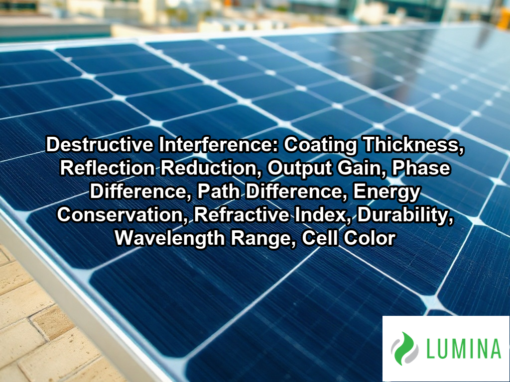
Destructive interference occurs when two light waves meet out of phase and cancel each other, reducing the combined brightness. Key aspects include coating thickness, reflection reduction, output gain, phase difference, path difference, energy conservation, refractive index, durability, wavelength range, and cell color. In a solar cell, a thin anti-reflective coating splits incoming light into two reflected waves, one from the coating’s top surface and one from the silicon beneath it. The extra distance travelled by the second wave creates a path difference, which produces a phase difference of half a wavelength between the two reflections. When that phase difference is reached, the reflected waves cancel, and more light enters the cell instead of bouncing away. This is why coating thickness is usually set near a quarter of the target wavelength inside the coating material, often tuned to the red-to-green range where sunlight is strongest. Your solar panels in DC benefit from this effect through reduced reflection loss and a measurable output gain, topics the sections below explain in turn.
Key Takeaways
- Uncoated silicon reflects about 30-35 percent of incoming light.
- A 180 degrees phase difference is needed for full destructive interference.
- Silicon nitride coating thickness of 70-80 nm reduces cell reflection losses.
- Porous silica glass coating thickness of 100-130 nm boosts output by 1-3 percent.
- Textured surfaces plus anti-reflective coating lower total reflection to 2-5 percent.
How Much Reflection Does Destructive Interference Remove Compared to Uncoated Silicon?
Destructive interference removes a significant portion of reflection from a solar cell, reducing the baseline reflection of uncoated silicon from 30-35 percent down to 10 percent or less. According to the National Renewable Energy Laboratory, uncoated silicon solar cells typically reflect more than 30 percent of incident sunlight, a loss that anti-reflective coatings utilizing destructive interference are designed to mitigate. By applying a silicon nitride coating, you fundamentally alter the way light behaves at the surface of the solar cell. This process uses the principle of destructive interference to ensure that the reflected wave from the top of the coating cancels out the reflection occurring at the interface with the silicon beneath it.
Typical Reflection Levels by Surface State
When you combine these specialized coatings with surface texturing, you can further minimize losses to reach a total reflection level of roughly 2-5 percent. The following table highlights how these adjustments modify the light-handling capability of your solar equipment:
| Surface State | Typical Reflection Level |
|---|---|
| Uncoated Silicon | 30-35 percent |
| Coated Silicon (Silicon Nitride) | 10 percent or less |
| Textured Surface with Coating | 2-5 percent |
Because the effectiveness of this cancellation depends on specific wavelengths, you should evaluate the spectral response of your chosen solar technology to see how well it suppresses reflection across the full visible light range.
To optimize the effectiveness of these anti-reflective measures, consider these additional factors:- Match the coating thickness to the peak intensity of the solar spectrum to ensure maximum destructive interference.
- Apply random pyramid texturing to increase the probability of secondary light capture through multiple surface reflections.
- Ensure precise control of the refractive index during the chemical vapor deposition process to prevent unintended phase shifts.
How Thick Is the Anti-Reflective Coating on a Solar Cell That Relies on Destructive Interference?
To minimize reflection losses through destructive interference, you should ensure the anti-reflective coating on a solar cell features a quarter-wave thickness, which for a standard silicon nitride coating typically ranges from about 70-80 nm to achieve the required 180 degrees of phase difference.
Anti-Reflective Coating Thickness Ranges (nm)
Silicon Nitride Coating on the Solar Cell
The anti-reflective coating on a solar cell that relies on destructive interference is typically between 70-80 nm thick. This precise measurement is required to ensure that reflected light waves from the coating surface and the underlying silicon layer create the necessary phase difference for cancellation. Per the University of California Santa Barbara, to minimize reflection for the peak intensity of the solar spectrum, the coating thickness is generally engineered to be between 70 and 100 nanometers.
Why Quarter-Wave Thickness Sets the 70-80 nm Target
To achieve destructive interference, the coating must reach a quarter-wave thickness relative to the incident light. When the optical thickness is one-fourth of the wavelength, the round-trip path difference equals half a wavelength. This causes the crest of the wave reflecting from the top of the coating to align with the trough of the wave reflecting from the silicon, resulting in minimized reflection. The following table summarizes the typical parameters for this process:
| Parameter | Standard Value |
|---|---|
| Coating thickness | 70-80 nm |
| Refractive index | Near 1.9-2.0 |
| Phase difference | 180 degrees |
Porous Silica Glass Coating on the Module Glass
Porous silica glass coating on the module glass is applied with a thickness of about 100-130 nm. This material serves a similar purpose by manipulating the refractive index at the interface between air and the glass surface. By maintaining this thickness, the coating effectively reduces reflection losses across the visible spectrum.
Why Does Refractive Index Matter for Coating Thickness?
The refractive index determines the speed at which light travels through the anti-reflective coating, which directly influences the path difference. If the refractive index deviates from the ideal range of 1.9-2.0, the effective optical thickness changes, shifting the wavelength at which destructive interference occurs. Proper index matching ensures the waves remain synchronized for maximum intensity reduction.
Inspect the specific spectral response curve of your solar panels to determine if the coating thickness is optimized for the wavelengths most prevalent in your local environment.
Additional considerations for optimizing anti-reflective coating performance include the following factors:- Surface texturing: Creating micro-pyramid structures on the silicon surface helps trap light through multiple reflections before it exits.
- Layer Multiplicity: Applying multiple thin-film layers with varying refractive indices can broaden the spectral range of anti-reflective performance.
- Angle of Incidence: Adjusting the coating thickness can compensate for off-axis light absorption to maintain efficiency throughout the day.
- Interface Matching: Ensuring the refractive index of the coating sits between that of air and silicon reduces the initial impedance mismatch.
How Path Difference of Half a Wavelength Creates Destructive Interference in a Solar Cell Coating
Path difference of half a wavelength creates destructive interference in a solar cell coating by forcing the reflected light waves to overlap with their crests and troughs in perfect opposition. When you apply an anti-reflective coating of the correct thickness, the light that reflects from the top surface and the light that reflects from the underlying silicon must travel different distances. Because the second wave travels through the coating twice—once inward and once outward—this total extra path difference allows the waves to emerge at the top surface exactly out of sync. Per American Physical Society, this effect occurs when the film thickness is controlled to an approximation of one-quarter of the incident light’s wavelength. When this path difference equals half of the wavelength of the incident light, the waves interfere in the following ways:
| Optical Phenomenon | Physical Mechanism | Resulting Wave Behavior |
|---|---|---|
| Phase Opposition | 180-degree shift via path difference | Peak aligns with trough |
| Amplitude Cancellation | Superposition of inverted vectors | Net displacement of zero |
| Energy Redistribution | Conservation of electromagnetic flux | Increased internal current potential |
| Spectrum Sensitivity | Thickness-to-wavelength proportionality | Frequency-specific interference |
- Phase Opposition: The 180-degree phase difference causes the wave peak of the first reflection to align precisely with the wave trough of the second reflection.
- Amplitude Cancellation: By combining these opposing movements, the system results in a net displacement of zero, effectively nullifying the reflected wave’s intensity.
- Energy Redistribution: Because energy cannot be destroyed, the canceled light energy is redirected into the material to enhance the potential current within the solar cell.
- Spectrum Sensitivity: The effectiveness of this process depends on the wavelength; a coating designed for 600 nm light will yield optimal destructive interference only near that specific color range.
Examine the intended wavelength of the light your panel is designed to capture, as this determines the precise dimensions required for the coating to remain effective.
The following sequence details the necessary physical conditions required to achieve effective destructive interference in solar cell anti-reflective coatings:- Calculation of the optimal refractive index, which should ideally be the square root of the substrate’s refractive index to ensure balanced reflection amplitudes.
- Maintenance of precise film uniformity across the entire cell surface to prevent localized interference failures.
- Selection of specific material coating compositions to minimize absorption losses while maximizing phase shifting capabilities.
- Alignment of the coating thickness to match the wavelength of the solar spectrum region where the silicon cell demonstrates peak conversion efficiency.
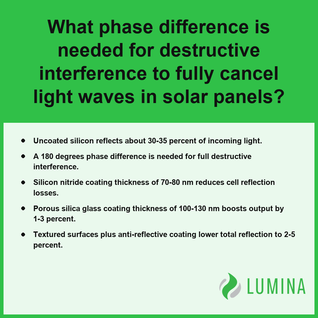
What Phase Difference Is Needed for Destructive Interference to Fully Cancel Light Waves in Solar Panels?
The phase difference required to achieve total cancellation of light waves through destructive interference is exactly 180 degrees, or π radians. When this phase condition is met, the crest of one reflected wave aligns perfectly with the trough of another, resulting in the complete suppression of the reflected light amplitude.
| Physical Parameter | Role in Destructive Interference | Technical Requirement for Null Intensity |
|---|---|---|
| Phase Shift | Wave Alignment | Exactly 180 degrees (π radians) |
| Optical Thickness | Path Length Control | Odd number of half-wavelengths (m + 0.5)λ |
| Refractive Index | Amplitude Matching | Balanced magnitude of reflected wave components |
| Angle of Incidence | Effective Path Variation | Maintenance of path symmetry to preserve phase |
- Ensure the incoming light waves have equal amplitudes, as even a minor imbalance prevents the intensity from reaching zero. Per National Institute of Standards and Technology, complete cancellation of electromagnetic waves through destructive interference is an approximation that requires interacting wave components to possess equal amplitude and a phase shift that puts the crest of one wave into alignment with the trough of the other.
- Design the anti-reflective coating to an optical thickness that forces a path difference equivalent to an odd number of half-wavelengths, specifically (m + 1/2)λ.
- Align the peaks and valleys of the waves so that the phase difference between the reflection from the top of the coating and the reflection from the underlying surface is exactly 180 degrees.
- Adjust the refractive index of the material to manage the intensity of each reflected wave, ensuring that the two reflections match in strength to facilitate full destructive interference.
Monitor how variations in the angle of incidence change the effective path difference, as maintaining this 180-degree phase difference becomes more complex when light does not strike the surface perpendicularly.
To optimize the performance and precision of anti-reflective coatings, consider these additional practical design requirements:- Apply a thin-film deposition technique such as physical vapor deposition to ensure uniform layer thickness across the substrate surface.
- Select materials with a refractive index that satisfies the quarter-wave matching condition, typically defined as the square root of the product of the incident medium and substrate indices.
- Incorporate multi-layer stacks to broaden the spectral range over which destructive interference effectively suppresses reflection.
- Account for the dispersion characteristics of the coating material to maintain the phase shift requirement across the intended bandwidth of light.
How Much Extra Power Can a Solar Module Gain From Destructive Interference Coatings on Its Glass?
The extra power a solar module gains from destructive interference coatings on its module glass typically ranges from 1 to 3 percent of the total output. By applying a porous silica glass coating, you reduce reflection losses at the air-glass interface, which allows more light to reach the internal solar cell. This improvement relies on the physical properties of the coating, specifically its thickness and refractive index, to ensure that incoming light waves undergo destructive interference upon reflection.
Typical Performance Gains
| Performance Metric | Impact of Porous Silica Glass Coating |
|---|---|
| Coating Thickness | 100-130 nm |
| Light Transmission Gain | Roughly 2-3 percentage points |
| Module Power Increase | About 1-3 percent |
While the boost to total module output may appear modest, these gains are cumulative across the entire surface area of your solar array. Per the Department of Energy, research into nanostructured surface treatments shows that these destructive interference techniques can improve light collection efficiency across a broader spectrum of incident angles, helping to enhance performance during early morning and late afternoon hours. Because the effect is optimized for specific wavelengths and light paths, you should evaluate the installation site’s seasonal sun orientation to determine if the coating’s performance will be maximized throughout the year.
Inspect the clarity and condition of your module glass periodically to ensure that dust or debris does not interfere with the light transmission pathways established by the coating.
To ensure the long-term effectiveness of antireflective coatings, consider these maintenance and environmental factors:- Clean the glass surfaces periodically using deionized water and non-abrasive cloths to prevent dust accumulation from scattering incident light.
- Avoid using harsh chemical solvents or acidic cleaners that may degrade the porosity of the silica structure.
- Monitor the coating for signs of delamination or physical wear caused by persistent exposure to high-velocity airborne particulates or extreme weather conditions.
- Verify that local environmental humidity levels remain within the manufacturer’s specified range to prevent moisture-induced degradation of the coating’s refractive index.
Frequently Asked Questions
Where does the energy go when destructive interference cancels reflected light on a solar panel?
Energy is not destroyed when destructive interference occurs; instead, it is redistributed to locations of constructive interference. Total energy across the entire pattern is conserved. Because intensity is proportional to amplitude squared, the energy that would have been reflected is instead directed into the material to enhance its overall efficiency.
Why does silicon nitride work for destructive interference on solar cells, and what refractive index does a coating need?
A silicon nitride coating works for destructive interference by utilizing a thickness of about 70-80 nm to cancel reflections, with an ideal refractive index near 1.9-2.0. This index is approximately the square root of the product of the air and silicon refractive indices, which effectively minimizes initial reflection losses.
Why does a single quarter-wave destructive interference coating only work well at one wavelength, and how do multilayer coatings fix it?
A single quarter-wave thickness coating functions at one wavelength and incident angle because it relies on a specific path difference to achieve a phase difference of 180 degrees. Multilayer or graded-index coatings broaden this effect by combining multiple interference patterns, ensuring that light across the entire solar spectrum experiences reduced reflection.
Why do solar panels look deep blue or black because of destructive interference?
Solar panels look deep blue or black because an anti-reflective coating tuned for destructive interference primarily cancels reflection in the green-red portion of the visible light spectrum. Because the longer wavelengths are suppressed, the remaining reflected light appears blue, preventing the silvery gray appearance characteristic of untreated, highly reflective silicon surfaces.
Do anti-reflective coatings that use destructive interference wear out over a solar panel’s 25-year life?
Yes, anti-reflective coatings that use destructive interference can experience degradation over time, though their stability depends on environmental exposure. By using materials like porous silica glass coating, about 100-130 nm thick, manufacturers aim to maintain the increased light transmission of 2-3 percentage points and the associated 1-3 percent output gain.