
Open Circuit Voltage: Temperature Effect, Typical Values, Measurement Method, String Length Limits, Code Requirements, Rated Conditions, Fault Diagnosis, Irradiance Response, Degradation and Safety
Open circuit voltage is the maximum voltage a solar panel produces when its terminals are not connected to any load. Key aspects include typical values, temperature effect, string length limits, measurement method, rated conditions, code requirements, irradiance response, fault diagnosis, and degradation and safety. You can think of it as the electrical pressure a panel builds in sunlight when no current flows, and it is usually printed on the panel label as Voc. Cell temperature and sunlight level change it, with colder cells producing a higher reading than warm ones. Knowing this number matters for solar panel installation Pennsylvania, where cold winter mornings can push voltage well above the figure listed on the datasheet. This article explains typical values, the temperature effect, how you measure it with a multimeter, the standard test conditions behind the rating, and how it sets the maximum number of panels in a string.
Key Takeaways
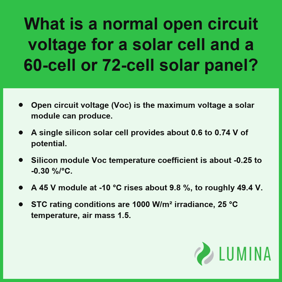
- Open circuit voltage (Voc) is the maximum voltage a solar module can produce.
- A single silicon solar cell provides about 0.6 to 0.74 V of potential.
- Silicon module Voc temperature coefficient is about -0.25 to -0.30 %/°C.
- A 45 V module at -10 °C rises about 9.8 %, to roughly 49.4 V.
- STC rating conditions are 1000 W/m² irradiance, 25 °C temperature, air mass 1.5.
What Is a Normal Open Circuit Voltage for a Solar Cell and a 60-Cell or 72-Cell Solar Module?
Under Standard Test Conditions (STC), you will find that a single silicon solar cell has an open circuit voltage (Voc) of about 0.6 to 0.74 V, while a typical 60-cell solar module ranges from about 36 to 41 V and a 72-cell solar module typically measures even higher.
Typical Open Circuit Voltage (Voc) by Cell Architecture
Open Circuit Voltage (Voc) of a Single Silicon Cell
The normal open circuit voltage (Voc) for a single silicon solar cell ranges from about 0.6 to 0.74 V, depending primarily on the manufacturing technology used. This voltage is an intrinsic property of the silicon material and its bandgap, meaning it remains consistent regardless of the physical surface area of the cell. Larger cells generate more short-circuit current (Isc) but do not increase the voltage output.
Different cell architectures produce slightly different voltage profiles under standardized conditions:
- Monocrystalline PERC cells: typically reach 0.65 to 0.70 V.
- Heterojunction cells: typically reach 0.72 to 0.75 V.
How Does Cell Count Change Module Voc?
The open circuit voltage (Voc) of a solar module increases as a direct result of wiring individual cells in series, where the total voltage is the sum of the individual cell potentials. Because cells are connected in a continuous series circuit within the frame, adding more cells creates a higher total potential difference across the module output leads.
Typical Voc Ranges for 60-Cell and 72-Cell Modules
| Module Configuration | Typical Open Circuit Voltage (Voc) |
|---|---|
| 60-Cell Module | 36 to 41 V |
| 72-Cell Module | 43 to 50 V |
| 132-Half-Cut (approx. 400–450 W) | 40 to 45 V |
Per the National Renewable Energy Laboratory, standard 72-cell solar modules typically demonstrate an open circuit voltage ranging from approximately 40 to 48 volts. It is important to note that the open circuit voltage (Voc) is always higher than the maximum power point voltage (Vmp), typically by about 15 to 20 %, reflecting the difference between a loaded and unloaded state. Always verify your specific module’s datasheet to confirm how its unique cell count aligns with your system’s design requirements.
Several external factors can cause the actual open circuit voltage of a solar module to deviate from these standard laboratory ratings:- Temperature: Voltage is inversely proportional to temperature; as cells heat up, the Voc decreases significantly.
- Irradiance: While Voc is less sensitive to light intensity than current, very low light conditions will cause a measurable drop in voltage.
- Degradation: Over the lifespan of a module, chemical and physical breakdown of the silicon lattice results in a gradual, permanent reduction in maximum voltage.
- Interconnect Resistance: Quality of the busbars and soldering between cells can introduce minor voltage drops due to internal electrical resistance.
What Open Circuit Voltage (Voc) on a Datasheet Means and How Standard Test Conditions (STC) Set the Rating
The open circuit voltage (Voc) on a datasheet represents the maximum electrical potential a solar module can generate when no current is flowing through the circuit, measured specifically under Standard Test Conditions (STC). Because actual field conditions rarely match these precise laboratory benchmarks, the datasheet provides this figure as a baseline for system designers to ensure the voltage remains within safe limits for connected equipment. Under STC, the rating is established using a standardized environment characterized by an irradiance of 1000 W/m², a cell temperature of 25 °C, and an air mass of 1.5. Per the International Electrotechnical Commission, these conditions serve as the industry-standard approximation for defining the measurement environment for nominal Voc. This calibration allows for consistent comparison between different modules regardless of their physical size or manufacturing origin.
| Voltage State | Relative Potential (% of Voc) | Operational Context |
|---|---|---|
| Open Circuit Voltage (Voc) | 100% | Maximum potential with zero current flow |
| Maximum Power Voltage (Vmp) | 80% – 85% | Voltage output during active energy delivery |
| Note: Electrical equipment must be sized for 100% Voc to prevent component failure during no-load conditions. | ||
Voltage Parameter Comparison (Percentage of Voc)
The following parameters define the environment required to achieve the nominal open circuit voltage (Voc) rating found on a manufacturer’s nameplate:
- Irradiance: 1000 W/m² (representing clear, direct midday sunlight)
- Cell Temperature: 25 °C (the standardized thermal baseline)
- Air Mass: 1.5 (the standardized atmospheric light-filtering factor)
Because the open circuit voltage (Voc) is typically 15 to 20 % higher than the maximum power point voltage (Vmp), you must ensure your electrical components are rated to handle the higher voltage potential rather than the operating voltage to prevent equipment failure during periods of low load. Verify that the sum of the open circuit voltage (Voc) for all modules in your series string, adjusted for the lowest expected ambient temperature, remains below the maximum DC input rating of your inverter.
The following factors significantly influence real-world voltage performance relative to the nominal datasheet rating:- Temperature fluctuations: Lower ambient temperatures cause the internal voltage to rise above the STC rating.
- Irradiance variability: Fluctuations in sunlight intensity primarily impact current, with only minor associated shifts in voltage.
- Aging degradation: Micro-cracks and material oxidation over time lead to a gradual reduction in the maximum potential of the cells.
- Spectral response: Variations in the light spectrum due to atmospheric conditions can alter the voltage output compared to the standardized AM 1.5 benchmark.
Why Open Circuit Voltage (Voc) Rises in Cold Weather
Open circuit voltage (Voc) rises in cold weather because the physical properties of the semiconductor material in the solar cells are temperature-sensitive. Per Sandia National Laboratories, the reduction in thermal energy at lower temperatures increases the band gap of the material, which approximately explains why the open-circuit voltage output rises. As the cell temperature drops, the internal resistance within the silicon decreases, allowing the solar module to generate a higher potential difference across its terminals. Because silicon modules typically have a temperature coefficient of about -0.25 to -0.30 %/°C for open circuit voltage (Voc), every degree of cooling below the Standard Test Conditions (STC) baseline results in a predictable upward shift in voltage. This effect is significant enough that a cold morning can push the operating voltage well above the nameplate rating specified for 25 °C, potentially exceeding the limits of your connected hardware if you do not account for these extreme low-temperature scenarios during design.
Open Circuit Voltage (Voc) Comparison
| Condition | Typical Effect on Voc |
|---|---|
| Temperature Drop | Voltage increases (Negative Temperature Coefficient) |
| Temperature Rise | Voltage decreases |
| 45 V Module at -10 °C | Increases by roughly 9.8% to 49.4 V |
You must verify the coldest historical temperature in your region and apply the module’s temperature coefficient to the open circuit voltage (Voc) to ensure the total string voltage never exceeds the inverter maximum DC input during a freezing event.
To ensure your electrical system remains safe during extreme cold, follow these design considerations:- Consult the module’s datasheet to identify the specific voltage temperature coefficient (βVoc) provided by the manufacturer.
- Calculate the worst-case voltage by applying the coefficient to the difference between your region’s record low temperature and the STC baseline of 25°C.
- Verify that the calculated maximum voltage does not exceed the maximum input voltage rating of your charge controller or grid-tied inverter.
- Adjust your string sizing to include fewer modules in series if the predicted winter voltage exceeds the hardware’s safety limits.
How to Measure Open Circuit Voltage (Voc) on a Solar Module with a Multimeter
You measure the open circuit voltage (Voc) on a solar module with a multimeter by isolating the panel from the system and probing its electrical terminals while the unit is exposed to sunlight. Because the open circuit voltage (Voc) represents the maximum potential difference when no current flows, you must ensure the circuit is fully disconnected from any load, such as an inverter or charge controller, to obtain an accurate reading.
| Measurement Stage | Technical Requirement | Safety & Accuracy Justification |
|---|---|---|
| Circuit Isolation | Full disconnection from load | Prevents current flow; required for valid Voc potential reading. |
| Multimeter Configuration | Range: 200V+ DC; Impedance: ≥ 10MΩ | Ensures equipment safety and prevents circuit loading errors. |
| Probe Application | Firm contact with terminals | Secures stable connection; prevents arcing or intermittent data. |
| Variable Reconciliation | Compare against STC datasheet | Adjusts for environmental deviation (sunlight intensity/cell heat). |
| Physical Interface | Insulated leads with solar connectors | Maintains electrical integrity and eliminates shock hazards. |
- Disconnect the solar module leads from the rest of your system to ensure zero current is flowing through the wires.
- Set your multimeter to the DC voltage setting, selecting a range that can accommodate the expected voltage, such as 200 V or higher for a typical residential module. Per the American Society for Testing and Materials, a digital multimeter used for this purpose should feature an input impedance of at least 10 megohms to minimize current draw and avoid measurement errors.
- Firmly press the positive (red) multimeter probe against the positive connector of the module and the negative (black) probe against the negative connector.
- Observe the stable reading on the multimeter screen; if the display is negative, simply reverse the positions of the probes.
- Compare this reading against the datasheet value provided for Standard Test Conditions (STC), keeping in mind that actual sunlight levels and cell temperature will cause the measured value to deviate from the factory rating.
Use an insulated pair of test leads with specialized solar connectors to maintain a secure, shock-free connection while you verify the reading on the display.
Follow these additional precautions to ensure consistent and reliable testing results:- Verify the meter leads are securely inserted into the “COM” and “V” ports before touching the module terminals.
- Ensure the solar panel surface is free of debris, shade, or heavy dust to avoid artificially low voltage readings.
- Perform the measurement during peak solar noon to best approximate the standard test conditions listed on the module label.
- Check the physical condition of the MC4 or similar connectors for signs of corrosion or melting before attempting to probe them.
How to Calculate Maximum String Length from Open Circuit Voltage (Voc) and Inverter Maximum DC Input
Calculating the maximum string length from open circuit voltage (Voc) and inverter maximum DC input is a critical safety step to prevent permanent damage to your inverter from overvoltage, particularly during cold weather events. Because open circuit voltage (Voc) rises as temperatures drop, you must use the lowest expected ambient temperature for your region to calculate the highest possible voltage your string will produce. Per National Electrical Code, systems must be sized so that the cumulative open-circuit voltage of a series string stays below the inverter’s maximum DC input rating during the coldest ambient conditions.
| Calculation Variable | Data Source / Reference | Role in Overvoltage Protection |
|---|---|---|
| Module Open Circuit Voltage (Voc) | Manufacturer Datasheet (STC) | Establishes the baseline voltage at 25 °C. |
| Temperature Coefficient (Voc) | Manufacturer Datasheet | Determines the percentage voltage increase per degree Celsius drop. |
| Lowest Ambient Temperature | Historical Meteorological Records | Identifies the worst-case thermal condition for voltage peaking. |
| Inverter Max DC Input | Inverter Nameplate / Datasheet | Sets the hard safety ceiling for the entire series string. |
| Temperature Derating Table | Manufacturer Technical Bulletin | Provides precision corrections for non-linear thermal responses. |
- Identify the module’s rated open circuit voltage (Voc) and its temperature coefficient from the datasheet.
- Determine the lowest historical ambient temperature for your installation site and calculate the temperature difference from the Standard Test Conditions (STC) of 25 °C.
- Adjust the Voc upward using the temperature coefficient to estimate the maximum possible voltage at that extreme cold temperature.
- Divide the inverter maximum DC input (such as 600 V for many older residential systems) by the adjusted module Voc to find the maximum theoretical number of modules.
- Round down to the nearest whole number to ensure the string voltage remains safely below the equipment limit.
Always verify the manufacturer’s specific temperature derating table if provided, as this often offers a more precise adjustment than a simple linear calculation using the temperature coefficient.
Follow these steps to complete the calculation of the maximum allowable modules per string:- Determine the temperature difference between the standard 25 °C test condition and your region’s lowest expected ambient temperature.
- Calculate the voltage increase factor by multiplying the temperature difference by the module’s voltage temperature coefficient.
- Apply the coefficient to the rated Voc to determine the maximum voltage the module will reach under extreme cold.
- Divide the inverter’s maximum DC input voltage by the adjusted module voltage to find the absolute string size limit.
- Round the result down to the nearest whole number to ensure the string stays strictly within safety parameters.
Frequently Asked Questions
How does the National Electrical Code 690.7 require open circuit voltage to be corrected for low temperatures?
The requirement for correcting open circuit voltage (Voc) for low temperatures involves ensuring the cold-temperature-corrected string Voc remains below the inverter maximum DC input. Because silicon modules have a temperature coefficient of about -0.25 to -0.30 %/°C, cold weather causes a voltage rise that must not exceed the system limits.
Does open circuit voltage change in low light or on cloudy days for a solar panel?
Yes, open circuit voltage (Voc) changes in low light, though only logarithmically. At 200 W/m² of irradiance, the Voc falls only about 10 to 15 % below the value recorded at full sun under Standard Test Conditions (STC), meaning a panel in dim light can still show a near-normal reading.
What does a low open circuit voltage reading on a solar string mean, and can normal Voc still hide a bad panel?
A low open circuit voltage (Voc) reading indicates a potential failure, and yes, a normal reading can hide a bad solar module. Because Voc does not reflect actual power output, a module can display a standard voltage while delivering little current under load, necessitating checks of short-circuit current (Isc) and Vmp.
Does the open circuit voltage of a solar panel decrease as the panel ages?
The open circuit voltage (Voc) of a solar panel can be affected by degradation, though it primarily depends on cell material and bandgap rather than panel size. While standard module performance may shift over time, Voc readings remain a measurement of the potential difference at zero current flow.
Why is open circuit voltage higher than the maximum power point voltage (Vmp) on a solar panel?
The open circuit voltage (Voc) is higher than the maximum power point voltage (Vmp) by usually about 15 to 20 % because Voc represents the peak potential when zero current flows. In contrast, Vmp accounts for internal resistance and load-based losses that occur when the device is actively generating power.